Showing posts with label Power Supply. Show all posts

Thursday, February 23, 2012

Test a car battery voltage using LM3914

|2 comments
This circuit uses the popular and easy to find LM3914 IC. This IC is very simple to drive, needs no voltage regulators (it has a built in voltage regulator) and can be powered from almost every source.

This circuit is very easy to explain:
When the test button is pressed, the Car battery voltage is feed into a high impedance voltage divider. His purpose is to divide 12V to 1,25V (or lower values to lower values). This solution is better than letting the internal voltage regulator set the 12V sample voltage to be feed into the internal voltage divider simply because it cannot regulate 12V when the voltage drops lower (linear regulators only step down). Simply wiring with no adjust, the regulator provides stable 1,25V which is fed into the precision internal resistor cascade to generate sample voltages for the internal comparators. Anyway the default setting let you to measure voltages betw1een 8 and 12V but you can measure even from 0V to 12V setting the offset trimmer to 0 (but i think that under 9 volt your car would not start). There is a smoothing capacitor (4700uF 16V) it is used to adsorb EMF noise produced from the ignition coil if you are measuring the battery during the engine working. Diesel engines would not need it, but i`m not sure. If you like more a point graph rather than a bar graph simply disconnect pin 9 on the IC (MODE) from power. The calculations are simple (default)
For the first comparator the voltage is : 0,833 V corresponding to 8 V
* * * * * voltage is : 0,875 V corresponding to 8,4 V
for the last comparator the voltage is : 1,25 V corresponding to 12 V

Tuesday, February 21, 2012

Circuit Receiver Battery Low Voltage Alarm

|0 comments

Here is another equally cool low voltage alarm circuit for your glider receiver battery that I've shamelessly stolen from George Steiner's book "A to Z--Radio Control Electronic Journal" (see below). I've modified it to use with small battery packs in R/C gliders. This design has a trigger voltage at about 4.3 volts, and it draws 1mA or less when quiet and about 4mA when buzzing. This can be constructed from parts fromt Radio Shack, though you may need to order a few through them.
The voltage of a receiver system is punctuated by low-voltage spikes every time the servo motors spin up, since the servos draw more than the battery can deliver. With large receiver battery packs, this is not as much of an issue, and it may not be noticeable. However with 270mA and smaller battery packs, particularly with more than two servos, low voltage alarms can chirp constantly, every time a servo moves. The challenge is to design in a little slack or delay, just enough so that you are not annoyed by constant chirping, but not too much so that the chirps can give you a warning before the battery is completely exhausted. Here, this "hysteresis" is adjusted with the capacitor. For large packs (600mA and above), no capacitor is probably needed, although I've been using a 1uF capacitor on my open class ship with 6 servos and a 600mA battery. For 270 mA and two servos, I'd suggest trying a 1uF capacitor. For 150mA or less, a 2.2uF capacitor works well. If you want to know only when the battery has finally reached the trigger voltage, try a 5uF (or 4.7uF) capacitor. The actual type of capacitor is not critical, but tantalum capacitors are physically smaller. If you want to worry about the polarity of the capacitor, the negative side should be directed toward the negative pole of the battery, but at these relatively low voltages compared to the capacitor rating, the polarity probably does not matter.
This circuit is set up for a four cell receiver battery pack at a trigger voltage of about 4.3 volts (about 1.1volts/cell). You can adjust R1 (here a 3.3k resistor) to change the trigger voltage of the circuit. For example, for a 5 cell pack, to change the trigger voltage to 5.5 volts, change R1 to 2.2k. For a three cell pack, to change the trigger voltage to 3.3 volts, change R1 to 6.8 k (or use two 3.3k resistors in parallel by soldering a resistor in each hole and twisting together the top leads). Because of slight variability in tolerances of the componants, you should check this little device with a variable power source and a voltmeter to confirm its trigger point. Alternately, use your digital voltmeter or expanded scale voltmeter to calibrate its chirp pattern by measuring the voltage of the onboard battery pack intermittently as you fly.
Make sure the band on the Zener diode is toward the "+" side (toward R1). Solder a battery connector or servo connector to the board with positive and negative as shown, and plug the connector into an unused slot in your receiver. 

 Circuit diagram

  
Radio Shack parts: Here again, you can use smaller rated resistors if you can get them--1/8 watt or less is fine. Tantalum capacitors are physically smaller, but any composition will work.
273-074 Miniature Piezo Buzzer, 12v, PC board mount
271-312 1/4 watt 5% carbon film resistors, 500 pieces (Take the plunge!)
276-1604 Package of 15 PNP small signal 2N3906-type transistors. Could use instead 276-2016 $0.59 2N3904 PNP transistors
RSU 11673505 3.3v Zener diode (not on shelf--need to order 1-800-THE-SHACK)
272-1434 1uf tantalum capacitor (see above for choice of capacitor)
RSU 11295888 2.2uF tantalum capacitor (not on shelf--need to order)
272-1024 4.7uF radial-lead electrolytic capacitor
Digikey (1-800-344-4539) part numbers: Digikey does sell the peizo buzzers, but they are much more expensive than those at Radio Shack and are larger as well.
2N3906-ND PNP general purpose amp/switch transistor
1N5226BMSCT-ND 3.3v Zener diode 500mA
3.3KEBK-ND 1/8 watt resistors
4.7KEBK-ND 1/8 watt resistors
10KEBK-ND 1/8 watt resistors
P2105-ND 1.0uF Tantalum capacitor 16volt
P2022-ND 2.2uF Tantalum capacitor 10volt
P2024-ND 4.7uF Tantalum capacitor 10 volt
FP012C-5-ND 3M clear 0.5" heat shrink tubing, 5 feet
author: Rob Crockett 10/99
e-mail:
web site:
http://www.electronics-lab.com

Sunday, February 19, 2012

POWERING A PROJECT

|0 comments

POWERING A PROJECT
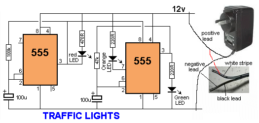
The safest way to power a project is with a battery. Use 4 x AA cells in a holder or a 9v battery if you only want to use the project for a short period of time.
If you want to use a 555 project for a long period of time you will need a "power supply."
The safest power supply is a Plug Pack (wall-wort, wall wart,
wall cube, power brick, plug-in adapter, adapter block, domestic mains adapter, power adapter, or AC adapter). The adapter shown in the diagram has a switchable output voltage: 3v, 6v, 7.5v, 9v, 12v) DC and is rated at 500mA. The black lead is negative and the other lead with a white stripe (or a grey lead with a black stripe) is the positive lead.
This is the safest way to power a project as the insulation (isolation) from the mains is provided inside the adapter and there is no possibility of getting a shock.
The rating "500mA" is the maximum the Plug Pack will deliver and if your circuit takes just 50mA, this is the current that will be supplied. Some pluck packs are rated at 300mA or 1A and some have a fixed output voltage. All these plug packs will be suitable.
Some Plug Packs are marked "12vAC."  This type of plug pack is not suitable for these circuits as it does not have a set of diodes and electrolytic to convert the AC to DC. All the circuits in this eBook require DC.

Saturday, February 11, 2012

Low-cost solution for the shipment of each of nickel, cadmium, and NiMH batteries

|0 comments
Low-cost solution for the shipment of each of nickel, cadmium, and NiMH batteries
Here is the schematic of a low-cost universal charger for NiCD - NiMH batteries. This circuit is ideal for car use. It has ability to transform a mains adapter for the charger. This can be used to recharge cell phones, toys, video batteries, MP3 players, ... and is selectable charging current. A LED is located in the circuit to indicate charging. Can be built on a breadboard or a general purpose PCB. Hope you like it.


Circuit diagram:
 Parts:

R1 = 120R-0...5W
R2 = See Diagram
C1 = 220uF-35V
D1 = 1N4007
D2 = 3mm. LED
Q1 = BD135
J1 = DC Input Socket

Specifications:
  • Ideal for in car use.
  • LED charge indication.
  • Selectable charge current.
  • Charges Ni Cd or NiMH batteries.
  • Transforms a mains adapter into a charger.
  • Charge cellular phone, toys, portables, video batteries …
 Features:
  • LED function indication.
  • Power supply polarity protected.
  • Supply current: same as charge current.
  • Supply voltage: from 6.5VDC to 21VDC (depending on used battery)
  • Charge current (±20%): 50mA, 100mA, 200mA, 300mA, 400mA. (selectable)
Determining the supply voltage:

This table indicates the minimum and maximum voltages to supply the charger. See supply voltage selection chart below.

Example:

To charge a 6V battery a minimum supply voltage of 12V is needed, the maximum voltage is then 15V.

Voltage selection:
Determining the charge current:

Before building the circuit, you must determinate how much current will be used to charge the battery or battery pack. It is advisable to charge the battery with a current that is 10 times smaller then the battery capacity, and to charge it for about 15 hours. If you double the charge current , then you can charge the battery in half the time. Charge current selection chart is located in diagram.

Example:

A battery pack of 6V / 1000mAh can be charged with 100mA during 15 hours. If you want to charge faster, then a charge current of 200mA can be used for about 7 hours.

Caution:

The higher charge current, the more critical the charge time must be checked. When faster charging is used, it is advisable to discharge the battery completely before charging. Using a charge current of 1/10 of the capacity will expand the lifetime of the battery. The charge time can easily be doubled without damaging the battery.

Note:
  • Mount the transistor together with the heatsink on the PCB, bend the leads as necessary. Take care that the metal back of the transistor touches the heatsink. Check that the leads of the transistor do not touch the heatsink.

circuit activate a relay by means of a hand clap

|0 comments
This circuit is intended to activate a relay by means of a hand clap. Further beats off of the relay. An unusual and interesting feature of this project is running on battery 3V. The sensitivity of the circuit has been intentionally reduced, to avoid the unpredictable operation. Therefore, the clapping of hands will be stronger they need to allow a constant on-off. Q1 acts as an audio amplifier. Timer IC1, wired as a monostable, provides a clean output signal and a delay of a reasonable time, in order to allow correct switching of the bistable circuit following. A discrete circuit components formed by Q2, Q3 and related parties has been used for this purpose, in order to drive the relay directly and to allow the operation 3V power supply.
Circuit Diagram:
 Clap Sensitive on-off Relay Circuit Diagram
 Parts:

R1 = 12K
R2 = 1M
R3 = 6.8K
R4 = 220K
R5 = 2.2M
R7 = 100K
R8 = 22K
R9 = 6.8K
R10 = 100K
Q1 = BC550C
Q2 = BC328
Q3 = BC328
C1 = 220nF-63V
C2 = 22nF-63V
C3 = 220nF-63V
C4 = 22nF-63V
C5 = 22nF-63V
C6 = 47uF-25V
D1 = 1N4148
D2 = 1N4148
B1 = 3V Battery
IC1 = 7555 CMos IC
RL1 = DIL Reed-Relay SPDT
SW1 = SPST Switch
MIC1 = Electret Mic


Notes:

A small DIL 5V reed-relay was used in spite of the 3V supply. Several devices of this type were tested and it was found that all of them were able to switch-on with a coil voltage value comprised in the 1.9 - 2.1V range. Coil resistance values varied from 140 to 250 Ohm. Stand-by current consumption of the circuit is less than 1mA. When the Relay is energized, current drain rises to about 20mA. 
Source: Red Free Circuit Design
tags: power supply, battery, Timer

Sunday, February 5, 2012

Circuit 12V Power Supply

|0 comments
Here is a simple 12V circuit, power is not easy to build the circuit at all. Simply by connecting the inter-connection as schematically attached with cables or son are properly shielded equipment. A beginner can assemble a schema is 12V in half an hour.


12V power supply circuit uses a transformer input 0-15V 3A AC. Unregulated DC supply voltage through a diode bridge integrated component and of the electrolyte capacitor. For a regulated DC voltage needs a 12V zener diode and a 2N3055 transistor with 3A maximum load current capabilities. Thus, the power supply circuit supplying 12V ​​fixed output voltage.


 To connect properly, you must know the pin out of the 2N3055, 2N3055 click to guide technical datasheet. For optimal heat 2N3055 transistor needs a heat sink attached to it. If you want an adjustable output voltage, it requires only small changes in input transistor 2N3055 base with a variable voltage. To this end, may use a LM723 IC. Caution in experimentation to a 12V supply circuit.

Tuesday, January 24, 2012

Adjustable Power Supply 0-15V / 5A

|0 comments
 Stabilized adjustable power supply 0-15V / 5A
 
This adapted ability accumulation can be adapted amid a few volts and 15V with P1 and with P2 acclimatize the high absolute ( 15.0V ). R6 amount is 0.7V / Imax area Imax is the best current. At Imax = 5A, R6 is 0.14Ω
T1 and T2 charge accept heatsinks because ability losses are abundant at a low achievement voltage and a Imax according accepted but you can affix the lamp L to abate this losses.
I’ve body this adjustable ability accumulation and works great! I achievement you’ll adore it too and accept fun body this abundant counterbalanced ability supply.

40 v 2A Power Supply Circuit

|0 comments


Power Supply Circuit using IC LM317


Circuit Diagram


Circuit Description

The primary part of this Power Supply circuit is the voltage regulator IC LM 317. This circuit is ideal for power circuits as the circuit of the power amplifier can deliver a current of 2A. In this circuit the transistor acts as a pass transistor Q1 to increase current capacity. The output voltage is set to 40V by using resistors R5 and R8.

Parts List

Resistors: R1 (39 ohm 1 or 2W Resistor)
R2 (22 ohm 1/4W Resistor)
R3 (68K 1/4W Resistor)
R4 (220R 1/4W Resistor)
R5 (47K 1/2W Resistor).

Capacitors: C1 (3300µF 50V Electrolytic Capacitor)
C2, C5 (100nF 63V Polyester Capacitors)
C3 (10µF 63V Electrolytic Capacitor)
C4 (220µF 50V Electrolytic Capacitor).

Active Components: D1 (Diode bridge 4A)
D2 (1N4002 Diode)
D3 (LED any color), U1 (LM317)
Q1 (TIP42A Transistor)
T1 (230V Primary, 40V 2A, Secondary, mains transformer).
 LM 317 PinOut

Converter Circuit 12V To 24V DC-DC

|0 comments

12V To 24V DC-DC Converter Circuit

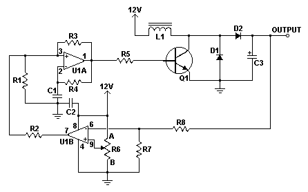
This simple DC-DC converter can provide up to 24V from a 12V source. It can be used to run radios, small lights, relays, horns and other 24V accessories from a 12V vehicle with a maximum draw of about 800mA. It can be used to charge one 12V battery from another, or step up the voltage just enough to provide necessary overhead for a 12V linear regulator. Using one op-amp as a squarewave oscillator to ring an inductor and another op-amp in a feedback loop, it won't drift around under varying loads, providing a stable 24V source for many applications. With a wide adjustment in output this circuit has many uses.
 Schematic

 Parts


Part

Total Qty.

Description

Substitutions
R1, R2, R3, R4, R8, R7 6 100K 1/4W Resistor
R5 1 470 Ohm 1/2W Resistor
R6 1 10K Linear Pot
C1 1 0.01uF Mylar Capacitor
C2 1 0.1uF Ceramic Disc Capacitor
C3 1 470uF 63V Electrolytic Capacitor
D1 1 1N4004 Rectifier Diode
D2 1 BY229-400 Fast Recovery Diode See Notes
Q1 1 BC337 NPN Power Transistor
U1 1 LM358 Dual Op Amp IC
L1 1 See Notes
MISC 1 Board, Wire, Socket For U1, Case, Knob For R6, Heatsink for Q1


    Notes

  1. R6 sets the output voltage. This can be calculated by Vout = 12 x (R8/(R8+R7)) x (R6B/R6A).
  2. L1 is made by winding 60 turns of 0.63MM magnet wire on a toroidial core measuring 15MM (OD) by 8MM (ID) by 6MM (H).
  3. D2 can be any fast recovery diode rated at greater then 100V at 5A. It is very important that the diode be fast recovery and not a standard rectifier.
  4. Q1 will need a heatsink.
Source: www.aaroncake.net

Sunday, January 22, 2012

3A regulated power supply with a stability

|0 comments

Regulated Power Supply with Stability at 3A

The circuit was designed to build a stable power supply the will provide a regulated voltage from 40 V to 70 V in a 3 A current.
  • 2N3055 – a complementary Silicon Epitaxial-Base planar NPN transistor mounted in Jedec TO-3 metal case for use as power transistor
  • BD243 – an epitaxial-base Silicon NPN transistor intended for wide variety of high speed switching and power amplifier applications such as series and shunt regulators, and driver and output stages of high-fidelity amplifiers
  • BC303 – a PNP silicon planar epitaxial transistor used for AF drivers & outputs, for AF medium power amplifiers, and for switching applications up to 1 A
 

 Figure 1

There are times when some applications are requiring a regulated power supply that has relatively high output voltage and stability. All of these features are being attained in the design of this circuit. The voltage output of the circuit can range from 40 V up to 60 V while carrying a current of 3 A while providing stabilization. The construction of the circuit is very simple since the components used were available easily in the market. The only thing that matters is how the connection will be ensured.
During the operation, when the circuit is delivering 50 V up to 60 V, the transistor Q1 will be hot enough and would require a large heatsink. For voltage output higher than 50 V up to 70 V, the stability of the circuit may be found unsatisfactory. This is the reason why the ideal output voltage of the circuit is 45 V up to 60 V. In order to alter the output voltage from 40 V up to 70 V, a 470 Ohms potentiometer RV1 is used for the adjustments. However, the potentiometer may also be replaced by two constant resistors with suitable values when the circuit adjustment has been done. This is due to the fact that the use of a potentiometer may lead to a 3 V of over voltage.
As a reminder, the positive output of the circuit should be connected at point A while the 0 V output should be connected at point B. The 0 V reference should not be connected to the ground for the circuit to function properly.
The use of this 3 A power supply with an average of 50 V circuit may be found on various applications that normally requires this rating. Since this type of circuit is easily built, it is being utilized in industrial, educational, clinical, and laboratory facilities. It may come with different additional features such as reduced ripple & noise, overload protection, and short circuit & high current protection.
Source:users.otenet.gr/~athsam/power_supply_50V_3A.htm

tags: power supply,  NPN transistor, switching

1A power supply with adjustable output of 0-15 volts

|0 comments
1A power supply with adjustable output of 0-15 volts
 Figure 1 

Terminology
  • 2N3055 – a complementary Silicon Epitaxial-Base planar NPN transistor mounted in Jedec TO-3 metal case for use as power transistor
  • Bridge Diode – also known as bridge rectifier which has four diodes arranged in a bridge configuration where the output voltage has the same polarity with either polarity of the input voltage
The construction of this power supply circuit is very simple in such a way that the components used are easy to be located while the cost is very cheap. With the biggest provided current at 1 A, the output voltage is adjusted for minimal ripple effect and stabilized in the range of 0 V to 15 V DC. This is made possible by the standard transformer output of 1.5 A with a primary winding voltage of 220 V and secondary voltage of 18 V. The current is being limited by the Zener diode D1 with a rating of 18 V and 1.5 W. The linear potentiometer R2 is responsible for the regulation of current.
The power transistor Q1 is a classic type that would require to be placed in a suitable heatsink to suppress the high heat dissipation during the operation of the circuit. The heat dissipation will be continuous during the presence of the highest current. The bridge diode GR1 will provide full wave rectification from the AC input which will also convert the incoming alternating current (AC) input into direct current (DC) output. One good feature of the bridge diode is maintaining the same polarity of the output regardless of the polarity of the input.

Figure 2 

The 15V/1 A power supply may be used to handle home automation control system which can be powered by 12 Vdc. They can be made into power adapter models to support a wide variety of applications such as TFT monitors, broadcasting, laptops, digital cameras, telecommunications, PSP’s, routers, notebooks, guitar effects pedals, KVM extenders, iPod’s, scanners, CCTV’s, printers, cassette players, radios, and other portable applications.
Source:users.otenet.gr/~athsam/power_supply_0_15v_1a.htm

DC Variable Regulator Power Supply

|0 comments

LM1458 and 2N3055 DC Variable Regulator Power Supply 

 Power ascendancy is adjustable 3-25 volts and is accepted bound to 2 amps as shown,but may be up to 3 amps in a baby accepted faculty resistor by options (0.3 ohm). 2N3055 transistors 2N3053 and should be in the sinks. actual hot appropriate now and resistor should be rated at 3 watts or more. voltage that is controlled by 1 / 2 of the op amp LM1458 or 1458-AMP. It may be commissioned in the ambit below, but sources advance pressure. dispensing pin 8 is bound to 30 VDC, which can access by 6.2 volt zener or 5.1 resistor K alternation is 8 pin. best voltage DC accumulation for 1458 and 1558 are 36 and 44, respectively. ability agent should be. As can be accepted in the accepted voltage. Enter at atomic 4 volts college than the adapted achievement voltage but not beat the best bulk of op-AMP beneath low amount conditions. Agent is apparent as a centermost broke 25.2 volt AC / AMP 2 units to advice ascendancy the 24 volts at 0.7 amps, 15 volts at 2 amps or 6 volts at 3 amps. Achievement AMP 3 is the centermost of the water. agent that changes the 18 volt position. All apparatus charge accept a Radio berth barring of LM1458 op-AMP.

5 to 15V Power Supply

|0 comments

5 to 15V 400mA Regulated Power Supply

This project is a simple DC regulated power supply that has a variable DC voltage range from 5V to 15V. It can supply current up to a 400mA to power the various circuits for your electronic projects. The voltage output is varied by using the potentiometer VR1. In this circuit, the input line power supply is designed for 240VAC. If 110VAC input is used, change the ratings of the varistor to 150VAC and the transformer ratio to 110V/12V.

Fuse F1 is used as a protection in case there is any short circuit in the circuit. Varistor V1 is connected in parallel to the input of the line voltage to clamp the surge voltage from the line to a reasonable level that helps to protect the transformer and other circuitry. Once the voltage level surge to a high level beyond the ability of the varistor to absorb it, fuse F1 or varistor V1 or both will burn. If this circuit failed after a period of operation, check that the fuse and the varistor are still in good condition or else replace them.


Diodes D1, D2, D3 and D4 are used to rectify the 12VAC voltage to DC voltage. Electrolytic capacitor E1 is used as a smoothing capacitor to reduce the ripple of the DC voltage. The DC voltage is fed into the input of 7805 regulator where the output DC voltage is obtained. Changing the value of VR1 will change the output of the DC voltage. Capacitor C1 is used to filter out high frequency component from the power supply.

Friday, January 14, 2011

simple Voltage Probe

|0 comments
Detects 1.8 to 230 Volts DC or AC

Minimum parts counting

Parts:

D1________5 or 3mm. Red LED
D2________5 or 3mm. Green or Yellow LED

LP1_______220V  6W  Filament Lamp Bulb

P1________Red Probe
P2________Black Probe

Device purpose:

This circuit is not a novelty, but it proved so useful, simple and cheap that it is worth building. When the positive (Red) probe is connected to a DC positive voltage and the Black probe to the negative, the Red LED will illuminate. Reversing polarities the Green LED will illuminate. Connecting the probes to an AC source both LEDs will go on. The bulb limits the LEDs current to 40mA @ 220V AC and its filament starts illuminating from about 30V, shining more brightly as voltage increases. Therefore, due to the bulb filament behavior, any voltage in the 1.8 to 230V range can be detected without changing component values.

Note:

  • A two colors LED (Red and Green) can be used in place of D1 & D2.

6VDC to 12VDC Converter

|0 comments

This is the circuit diagram of 6VDC to 12VDC Converter. With this circuit, you can doubled the input voltage of 6V DC to become 12V DC output voltage.
Component Parts:
R1, R4 = 2.2K
R2, R3 = 4.7K
R5 = 1K
R6 = 1.5K
R7 = 33K
R8 = 10K
C1,C2 = 0.1uF
C3 = 470uF/25V
D1 = 1N914
D2 = 1N4004
D3 = 12V 400mW Zener Diode
Q1, Q2, Q4 = BC547
Q3 = BD679
L1 See Notes


Circuit Notes:
1. L1 is a custom inductor wound with about 80 turns of 0.5mm magnet wire around a toroidal core with a 40mm outside diameter.
2. Different values of D3 can be used to get different output voltages from about 0.6V to around 30V. Note that at higher voltages the circuit might not perform as well and may not produce as much current. You may also need to use a larger C3 for higher voltages and/or higher currents.
3. You can use a larger value for capacitor C3 to provide better filtering.
4. The circuit will require about 2A from the 6V supply to provide the full 800mA at 12V.

6VDC to 12VDV Converter circuit, source:
Website: http://www.aaroncake.net

Tuesday, January 11, 2011

12V 30A Regulated Power Supply

|0 comments

Very high current regulated power supply. This circuit require a transformer which have output 24v / 35A. It should be an expensive circuit

Notes:
The input transformer is likely to be the most expensive part of the entire project. As an alternative, a couple of 12 Volt car batteries could be used. The input voltage to the regulator must be at least several volts higher than the output voltage (12V) so that the regulator can maintain its output. If a transformer is used, then the rectifier diodes must be capable of passing a very high peak forward current, typically 100amps or more. The 7812 IC will only pass 1 amp or less of the output current, the remainder being supplied by the outboard pass transistors. As the circuit is designed to handle loads of up to 30 amps, then six TIP2955 are wired in parallel to meet this demand. The dissipation in each power transistor is one sixth of the total load, but adequate heat sinking is still required. Maximum load current will generate maximum dissipation, so a very large heat sink is required. In considering a heat sink, it may be a good idea to look for either a fan or water cooled heat sink. In the event that the power transistors should fail, then the regulator would have to supply full load current and would fail with catastrophic results. A 1 amp fuse in the regulators output prevents a safeguard. The 400mohm load is for test purposes only and should not be included in the final circuit. A simulated performance is shown below:

1.3 - 32 V / 5A Power Supply w/ Short Circuit Protection

|0 comments

1.3 - 32 V / 5A Power Supply w/ Short Circuit Protection by LM338

Description

This is a very easy to build power supply that is based on LM338 5A adjustable voltage regulator. I am using the supply for a long time, have no problem yet. Only current adjust is missing but I overcome this situation by using an LCD panel ampermeter.
There is no PCB for the circuit. I took a 3x16 copper plate and strip the unused areas by a knife. If you want you can use analog meters instead of LCD panels. 


Notes

  • Use thick wires for connections.
  • When connecting the LM338 to the heatsink use thermal paste. 
  • Use external supplies for LCD panels. They can be 9V batteries. The panels I use draws 1mA current and the batteries last sufficiently long time. If you have small transformers which can supply regulated 9V, you can use them. You need separate transformers for each panel!
  • The transformer should be 100 Watt but if you don't need high current you can try transformers that you already have. (I can draw 6A from 100Watt transformer.)
  • If you have multi winding transformer you can use the diode connections shown in schematic. Diodes must be 10-15 A.
  • Be careful while connecting LM338. Don't put it inverse.
  • Output of your transformer mustn't exceed 25V AC.


This circuit operates with high power! Be careful while building and using it!
 
Source : www.circuit-projects.com

DC Power Supply with 13.8V and 20A

|0 comments

Overview

The circuit was designed to create a DC power supply that will be rated with 13.8 V and 20 A while having a current limiter and short circuit protection.


Terminology

  • Field Effect Transistor (FET) – used for amplifying weak signals by controlling the current and the shape of an electric field where the flow of current or the conductivity of material is only through a single type of semiconductor material
  • Diode Bridge – also known as bridge rectifier which has four diodes arranged in a bridge configuration where the output voltage has the same polarity with either polarity of the input voltage
  • BC547 – NPN small signal transistors designed for general purpose switching and amplification due to its low voltage, low current and three different gain selections
  • BC557 – PNP general purpose transistors used for amplification and switching due to its low current and low voltage
  • 2N5683 – high-current complementary Silicon power transistors designed for use in high-power amplifier and switching circuit applications
  • BD330 – PNP power transistor with high current and low voltage, used in power switching and amplification, especially in portable equipments
  • 7812 – 3-terminal 1A positive voltage regulator with short circuit protection, thermal overload protection, output transistor safe operating area protection, output current up to 1A, and output voltages from 5V to 24V

Circuit Explanation

By producing 13.8 Volts at around 20 Amps, the power supply unit is suitable for ham radio transceivers that are often receiving currents. A separate 15 mA to 20 A current limiting output has been added for lower currents. To achieve the desired voltage of 13.8V, the power transformer should be proficient enough to provide 17.5 V to 20 V at 25 A. Low power dissipation is the result of low voltage supply. Capacitor C1 smoothens the current form the diode bridge rectifier. To do this, the value of the capacitor should not be less than 40 uF or 50 uF. This is very true to the fact that 20 uF should be provided per ampere. It is not necessary to position a higher value capacitor, instead a parallel combination of smaller capacitors can be used to achieve the desired value.
The foundation of the circuit design is focused around the 7812 IC 12V regulator. The desired value of 13.8V can be calculated using the two attached resistors R5 and R6 with the formula: U=12(1+R5/R6). For the 7812 regulator to function properly, a low current of 15 mA should be maintained in the circuit. In the event that the current exceeds 15 mA, R4 will receive the voltage drop from the IC. This will cause Q3 2N5683 to open, which manages the high output current. As a PNP transistor, the factor for current amplification is at least 20.
A current limiting circuit is applied on this design with a resistance of 0.03 ohms for the maximum output of 20 A and a power rating of at least 15 W. To create such circuit, several resistors may be connected in parallel or a resistance wire that will give a total of the preferred resistance and power value. To compute for the resistance, the formula is used: RL=0.7/Imax. A short circuit automatic fuse can be created from the combination of RL and Q2, a 3A PNP BD330 which will be opened by the voltage drop across the resistor RL upon reaching the maximum current of 20 A. this will limit the base-emitter current of Q3. To provide an adjustable current source for smaller currents, an adjustable current limiter is placed in parallel to the fixed output.
LED1 will shed light with the aid of Q1 which is connected in parallel with Q2 while LED2 lights up in every switching ON of the PSU. IC1 can only be damaged with a full current flowing through it. This is due to the bridging of R3 by Q2 when the fuse is active. To prevent this from occurring, resistor R4 is included to limit the current of IC1 to 15 mA. The addition of resistor R4 will avoid IC1 from heating up, thus reducing the need for cooling aid.
The construction of the circuit is very simple that it does not require any current sensing resistor. But the same functionality exist in the form of the Rds-on resistance of the N-channel FET. It is responsible for handling the load cutoff from the source. The diagram 2 helps show how the FET functions. It behaves as a resistor but after a knick, it functions as constant current source. The knick is produced during the fast rise of the tension Uds across the resistance Rds due to the rising of current Id. The Uds voltage of the FET1 is detected by the R3, D2, and base-emitter connection for the Q4. The Q4 will stop the current flow through FET1 and provide shortcut for FET1 gate to mass and if the voltage rises enough. But then again, a certain voltage gate is necessary to enable the FET1 to open. This gate voltage will be supplied by the voltage divider which consists of R8, R9, Z1, and P1. With this, the minimal voltage will be around 3.6 V and the maximum gate voltage will be that of the Z1 which will identify the maximum current flowing through the FET1. As shown in the diagram, the current at 20 A should have around 9.6 V and for 5 A the Uz1 should be 5.6.
The reaction time or velocity of the limiter will be determined by the capacitor C4. A reaction time of around 100 ms will be made possible by the addition of 100 uF while adding 1 nF will make a reaction time of 1 us. The current output is limited in the range of 15 mA to 20 A with the operation of P1. The value of the RL will limit the total output current, although both outputs can be used simultaneously. If the transformer can handle higher current requirements, the PSU can de designed for higher outputs. This time Q3 will require enough cooling.

Application

The power supply unit having a fixed value of 13.8 VDC output and continuous running time of 90 mins is ideal for application with citizen’s band (CB) radio, auto equipment, and communications transceivers. It has short circuit and overload protection. It is also used for testing car audio amplifiers and other communications equipments since it has extremely low noise and ripple and excellent regulation.
Source:www.zen22142.zen.co.uk/Circuits/Power/13v820a.htm

Regulator 12V 10A

|0 comments
This is circuit regulator 12V 10A by IC 723+2N3055.
Q 2N3055 x 2 for to increase form IC LM723.
To use transformer 10A, Transistor to Hold Heatsink.
To adjust the output voltage simplyt by VR1 – 1K.
circuit Regulator 12V 10A by IC 723+2N3055
 A friend of me wants 12V Power supply for High Current 10A load. Me tries to search see meet this circuit will should is appropriate. Because of use IC LM723. Be the integrated circuit Voltage Regulator at good one although older already. But still be usable well. Fine decorate voltage output with well. Besides still have the transistor 2N3055 numbers are highly popular transistor again the one number. Make the all equipment of this circuit seeks easy certainly. If friends want to give 10A electric tall currents. Should use a pot transforms the sky that has 10A sizes with. For VR1 give for fine decorate voltage output get as well be can fine about 0-16V. The detail is other , please see in the circuit better.


Source: 97 Electron circuit
www.eleccircuit.com

12V 5A power supply Regulator

|0 comments
The basic car electrical system gives you around 12-13V when the engine is off and 13-14V when it is running. Not good for a computer, so the basic idea is to use a simple voltage which takes an unregulated voltage in and outputs a regulated voltage. The LM1084IT-12 is a 12V, 5A, Low dropout voltage regulator in a TO220 package to which a heatsink will be added. The low dropout feature is nice as the cars supply varies so much. regulator
Source: http://www.zorg.org/projects/carpc.php

555 Timer Circuit

Power Supply

Electronic Circuit Designer.