Bridge rectifier 

Example:
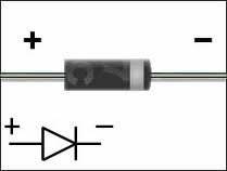
 Circuit symbol:
Function
Diodes allow electricity to flow in only one direction. The arrow of the circuit symbol shows the

direction in which the current can flow. Diodes are the electrical version of a valve and early diodes were actually called valves.
Forward Voltage Drop
Electricity uses up a little energy pushing its way through the diode, rather like a person pushing through a door with a spring. This means that there is a small voltage across a conducting diode, it is called the forward voltage drop and is about 0.7V for all normal diodes which are made from silicon. The forward voltage drop of a diode is almost constant whatever the current passing through the diode so they have a very steep characteristic (current-voltage graph).Reverse Voltage
When a reverse voltage is applied a perfect diode does not conduct, but all real diodes leak a very tiny current of a few µA or less. This can be ignored in most circuits because it will be very much smaller than the current flowing in the forward direction. However, all diodes have a maximum reverse voltage (usually 50V or more) and if this is exceeded the diode will fail and pass a large current in the reverse direction, this is called breakdown.Signal diodes (small current)
Signal diodes are used to process information (electrical signals) in circuits, so they are only required to pass small currents of up to 100mA.General purpose signal diodes such as the 1N4148 are made from silicon and have a forward voltage drop of 0.7V.

Source : http://robosapienv2-4mem8.page.tl