Showing posts with label Power Supply. Show all posts

Thursday, February 23, 2012

Test a car battery voltage using LM3914

|2 comments
This circuit uses the popular and easy to find LM3914 IC. This IC is very simple to drive, needs no voltage regulators (it has a built in voltage regulator) and can be powered from almost every source.

This circuit is very easy to explain:
When the test button is pressed, the Car battery voltage is feed into a high impedance voltage divider. His purpose is to divide 12V to 1,25V (or lower values to lower values). This solution is better than letting the internal voltage regulator set the 12V sample voltage to be feed into the internal voltage divider simply because it cannot regulate 12V when the voltage drops lower (linear regulators only step down). Simply wiring with no adjust, the regulator provides stable 1,25V which is fed into the precision internal resistor cascade to generate sample voltages for the internal comparators. Anyway the default setting let you to measure voltages betw1een 8 and 12V but you can measure even from 0V to 12V setting the offset trimmer to 0 (but i think that under 9 volt your car would not start). There is a smoothing capacitor (4700uF 16V) it is used to adsorb EMF noise produced from the ignition coil if you are measuring the battery during the engine working. Diesel engines would not need it, but i`m not sure. If you like more a point graph rather than a bar graph simply disconnect pin 9 on the IC (MODE) from power. The calculations are simple (default)
For the first comparator the voltage is : 0,833 V corresponding to 8 V
* * * * * voltage is : 0,875 V corresponding to 8,4 V
for the last comparator the voltage is : 1,25 V corresponding to 12 V

Tuesday, February 21, 2012

Circuit Receiver Battery Low Voltage Alarm

|0 comments

Here is another equally cool low voltage alarm circuit for your glider receiver battery that I've shamelessly stolen from George Steiner's book "A to Z--Radio Control Electronic Journal" (see below). I've modified it to use with small battery packs in R/C gliders. This design has a trigger voltage at about 4.3 volts, and it draws 1mA or less when quiet and about 4mA when buzzing. This can be constructed from parts fromt Radio Shack, though you may need to order a few through them.
The voltage of a receiver system is punctuated by low-voltage spikes every time the servo motors spin up, since the servos draw more than the battery can deliver. With large receiver battery packs, this is not as much of an issue, and it may not be noticeable. However with 270mA and smaller battery packs, particularly with more than two servos, low voltage alarms can chirp constantly, every time a servo moves. The challenge is to design in a little slack or delay, just enough so that you are not annoyed by constant chirping, but not too much so that the chirps can give you a warning before the battery is completely exhausted. Here, this "hysteresis" is adjusted with the capacitor. For large packs (600mA and above), no capacitor is probably needed, although I've been using a 1uF capacitor on my open class ship with 6 servos and a 600mA battery. For 270 mA and two servos, I'd suggest trying a 1uF capacitor. For 150mA or less, a 2.2uF capacitor works well. If you want to know only when the battery has finally reached the trigger voltage, try a 5uF (or 4.7uF) capacitor. The actual type of capacitor is not critical, but tantalum capacitors are physically smaller. If you want to worry about the polarity of the capacitor, the negative side should be directed toward the negative pole of the battery, but at these relatively low voltages compared to the capacitor rating, the polarity probably does not matter.
This circuit is set up for a four cell receiver battery pack at a trigger voltage of about 4.3 volts (about 1.1volts/cell). You can adjust R1 (here a 3.3k resistor) to change the trigger voltage of the circuit. For example, for a 5 cell pack, to change the trigger voltage to 5.5 volts, change R1 to 2.2k. For a three cell pack, to change the trigger voltage to 3.3 volts, change R1 to 6.8 k (or use two 3.3k resistors in parallel by soldering a resistor in each hole and twisting together the top leads). Because of slight variability in tolerances of the componants, you should check this little device with a variable power source and a voltmeter to confirm its trigger point. Alternately, use your digital voltmeter or expanded scale voltmeter to calibrate its chirp pattern by measuring the voltage of the onboard battery pack intermittently as you fly.
Make sure the band on the Zener diode is toward the "+" side (toward R1). Solder a battery connector or servo connector to the board with positive and negative as shown, and plug the connector into an unused slot in your receiver. 

 Circuit diagram

  
Radio Shack parts: Here again, you can use smaller rated resistors if you can get them--1/8 watt or less is fine. Tantalum capacitors are physically smaller, but any composition will work.
273-074 Miniature Piezo Buzzer, 12v, PC board mount
271-312 1/4 watt 5% carbon film resistors, 500 pieces (Take the plunge!)
276-1604 Package of 15 PNP small signal 2N3906-type transistors. Could use instead 276-2016 $0.59 2N3904 PNP transistors
RSU 11673505 3.3v Zener diode (not on shelf--need to order 1-800-THE-SHACK)
272-1434 1uf tantalum capacitor (see above for choice of capacitor)
RSU 11295888 2.2uF tantalum capacitor (not on shelf--need to order)
272-1024 4.7uF radial-lead electrolytic capacitor
Digikey (1-800-344-4539) part numbers: Digikey does sell the peizo buzzers, but they are much more expensive than those at Radio Shack and are larger as well.
2N3906-ND PNP general purpose amp/switch transistor
1N5226BMSCT-ND 3.3v Zener diode 500mA
3.3KEBK-ND 1/8 watt resistors
4.7KEBK-ND 1/8 watt resistors
10KEBK-ND 1/8 watt resistors
P2105-ND 1.0uF Tantalum capacitor 16volt
P2022-ND 2.2uF Tantalum capacitor 10volt
P2024-ND 4.7uF Tantalum capacitor 10 volt
FP012C-5-ND 3M clear 0.5" heat shrink tubing, 5 feet
author: Rob Crockett 10/99
e-mail:
web site:
http://www.electronics-lab.com

Sunday, February 19, 2012

POWERING A PROJECT

|0 comments

POWERING A PROJECT
The safest way to power a project is with a battery. Use 4 x AA cells in a holder or a 9v battery if you only want to use the project for a short period of time.
If you want to use a 555 project for a long period of time you will need a "power supply."
The safest power supply is a Plug Pack (wall-wort, wall wart,
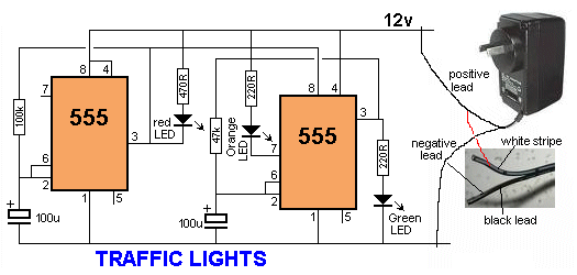
wall cube, power brick, plug-in adapter, adapter block, domestic mains adapter, power adapter, or AC adapter). The adapter shown in the diagram has a switchable output voltage: 3v, 6v, 7.5v, 9v, 12v) DC and is rated at 500mA. The black lead is negative and the other lead with a white stripe (or a grey lead with a black stripe) is the positive lead.
This is the safest way to power a project as the insulation (isolation) from the mains is provided inside the adapter and there is no possibility of getting a shock.
The rating "500mA" is the maximum the Plug Pack will deliver and if your circuit takes just 50mA, this is the current that will be supplied. Some pluck packs are rated at 300mA or 1A and some have a fixed output voltage. All these plug packs will be suitable.
Some Plug Packs are marked "12vAC."  This type of plug pack is not suitable for these circuits as it does not have a set of diodes and electrolytic to convert the AC to DC. All the circuits in this eBook require DC.

Saturday, February 11, 2012

Low-cost solution for the shipment of each of nickel, cadmium, and NiMH batteries

|0 comments
Low-cost solution for the shipment of each of nickel, cadmium, and NiMH batteries
Here is the schematic of a low-cost universal charger for NiCD - NiMH batteries. This circuit is ideal for car use. It has ability to transform a mains adapter for the charger. This can be used to recharge cell phones, toys, video batteries, MP3 players, ... and is selectable charging current. A LED is located in the circuit to indicate charging. Can be built on a breadboard or a general purpose PCB. Hope you like it.


Circuit diagram:
 Parts:

R1 = 120R-0...5W
R2 = See Diagram
C1 = 220uF-35V
D1 = 1N4007
D2 = 3mm. LED
Q1 = BD135
J1 = DC Input Socket

Specifications:
  • Ideal for in car use.
  • LED charge indication.
  • Selectable charge current.
  • Charges Ni Cd or NiMH batteries.
  • Transforms a mains adapter into a charger.
  • Charge cellular phone, toys, portables, video batteries …
 Features:
  • LED function indication.
  • Power supply polarity protected.
  • Supply current: same as charge current.
  • Supply voltage: from 6.5VDC to 21VDC (depending on used battery)
  • Charge current (±20%): 50mA, 100mA, 200mA, 300mA, 400mA. (selectable)
Determining the supply voltage:

This table indicates the minimum and maximum voltages to supply the charger. See supply voltage selection chart below.

Example:

To charge a 6V battery a minimum supply voltage of 12V is needed, the maximum voltage is then 15V.

Voltage selection:
Determining the charge current:

Before building the circuit, you must determinate how much current will be used to charge the battery or battery pack. It is advisable to charge the battery with a current that is 10 times smaller then the battery capacity, and to charge it for about 15 hours. If you double the charge current , then you can charge the battery in half the time. Charge current selection chart is located in diagram.

Example:

A battery pack of 6V / 1000mAh can be charged with 100mA during 15 hours. If you want to charge faster, then a charge current of 200mA can be used for about 7 hours.

Caution:

The higher charge current, the more critical the charge time must be checked. When faster charging is used, it is advisable to discharge the battery completely before charging. Using a charge current of 1/10 of the capacity will expand the lifetime of the battery. The charge time can easily be doubled without damaging the battery.

Note:
  • Mount the transistor together with the heatsink on the PCB, bend the leads as necessary. Take care that the metal back of the transistor touches the heatsink. Check that the leads of the transistor do not touch the heatsink.

circuit activate a relay by means of a hand clap

|0 comments
This circuit is intended to activate a relay by means of a hand clap. Further beats off of the relay. An unusual and interesting feature of this project is running on battery 3V. The sensitivity of the circuit has been intentionally reduced, to avoid the unpredictable operation. Therefore, the clapping of hands will be stronger they need to allow a constant on-off. Q1 acts as an audio amplifier. Timer IC1, wired as a monostable, provides a clean output signal and a delay of a reasonable time, in order to allow correct switching of the bistable circuit following. A discrete circuit components formed by Q2, Q3 and related parties has been used for this purpose, in order to drive the relay directly and to allow the operation 3V power supply.
Circuit Diagram:
 Clap Sensitive on-off Relay Circuit Diagram
 Parts:

R1 = 12K
R2 = 1M
R3 = 6.8K
R4 = 220K
R5 = 2.2M
R7 = 100K
R8 = 22K
R9 = 6.8K
R10 = 100K
Q1 = BC550C
Q2 = BC328
Q3 = BC328
C1 = 220nF-63V
C2 = 22nF-63V
C3 = 220nF-63V
C4 = 22nF-63V
C5 = 22nF-63V
C6 = 47uF-25V
D1 = 1N4148
D2 = 1N4148
B1 = 3V Battery
IC1 = 7555 CMos IC
RL1 = DIL Reed-Relay SPDT
SW1 = SPST Switch
MIC1 = Electret Mic


Notes:

A small DIL 5V reed-relay was used in spite of the 3V supply. Several devices of this type were tested and it was found that all of them were able to switch-on with a coil voltage value comprised in the 1.9 - 2.1V range. Coil resistance values varied from 140 to 250 Ohm. Stand-by current consumption of the circuit is less than 1mA. When the Relay is energized, current drain rises to about 20mA. 
Source: Red Free Circuit Design
tags: power supply, battery, Timer

555 Timer Circuit

Power Supply

Electronic Circuit Designer.