3. Coils and transformers
3.1 Coils
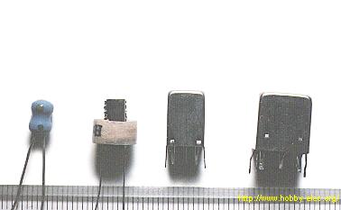
 Coils are not a very common component in electronic circuits, however when they are used, they need to be understood. They are encountered in oscillators, radio-receivers, transmitter and similar devices containing oscillatory circuits. In amateur devices, coils can be made by winding one or more layers of insulated copper wire onto a former such as PVC, cardboard, etc. Factory-made coils come in different shapes and sizes, but the common feature for all is an insulated body with turns of copper wire.
The basic characteristic of every coil is its inductance. Inductance is measured in Henry (H), but more common are millihenry (mH) and microhenry (µH) as one Henry is quite a high inductance value. As a reminder:
1H = 1000mH = 106 µH.
Coil inductance is marked by XL, and can be calculated using the following formula:
where f represents the frequency of the voltage in Hz and the L represents the coil inductance in H.
For example, if f equals 684 kHz, while L=0.6 mH, coil impedance will be:
The same coil would have three times higher impedance at three times higher frequency. As can be seen from the formula above, coil impedance is in direct proportion to frequency, so that coils, as well as capacitors, are used in circuits for filtering at specified frequencies. Note that coil impedance equals zero for DC (f=0).
Several coils are shown on the figures 3.1, 3.2, 3.3, and 3.4.
The simplest coil is a single-layer air core coil. It is made on a cylindrical insulator (PVC, cardboard, etc.), as shown in figure 3.1. In the figure 3.1a, turns have space left between them, while the common practice is to wind the wire with no space between turns. To prevent the coil unwinding, the ends should be put through small holes as shown in the figure.
Fig. 3.1: Single-layer coil
Figure 3.1b shows how the coil is made. If the coil needs 120 turns with a tapping on the thirtieth turn, there are two coils L1 with 30 turns and L2 with 90 turns. When the end of the first and the beginning of the second coil are soldered, we get a "tapping."
A multilayered coil is shown in figure 3.2a. The inside of the plastic former has a screw-thread, so that the ferromagnetic core in the shape of a small screw can be inserted. Screwing the core moves it along the axis and into the center of the coil to increase the inductance. In this manner, fine changes to the inductance can be made.
Fig. 3.2: a. Multi-layered coil with core, b. Coupled coils
Figure 3.2b shows a high-frequency transformer. As can be seen, these are two coils are coupled by magnetic induction on a shared body. When the coils are required to have exact inductance values, each coil has a ferromagnetic core that can be adjusted along the coil axis.
At very high frequencies (above 50MHz) coil inductance is small, so coils need only a few turns. These coils are made of thick copper wire (approx. 0.5mm) with no coil body, as shown on the figure 3.3a. Their inductance can be adjusted by physically stretching or squeezing the turns together.
Fig. 3.3: a. High frequency coil, b. Inter-frequency transformer
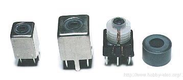
Figure 3.3b shows a metal casing containing two coils, with the schematic on the right. The parallel connection of the first coil and capacitor C forms an oscillatory circuit. The second coil is used for transferring the signal to the next stage. This is used in radio-receivers and similar devices. The metal casing serves as a screen to prevent external signals affecting the coils. For the casing to be effective, it must be earthed.
Fig 3.4 shows a "pot core" inductor. The core is made in two halves and are glued together. The core is made of ferromagnetic material, commonly called "ferrite." These inductors are used at frequencies up to 100kHz. Adjustment of the inductance can be made by the brass or steel screw in the centre of the coil.
Fig. 3.4: A "pot core" inductor
3.2 Transformers
For electronic devices to function it is necessary to have a DC power supply. Batteries and rechargeable cells can fulfill the role, but a much more efficient way is to use a POWER SUPPLY. The basic component of a power supplyr is a transformer to transform the 220V "mains" to a lower value, say 12V. A common type of transformer has one primary winding which connects to the 220V and one (or several) secondary windings for the lower voltages. Most commonly, cores are made of E and I laminations, but some are made of ferromagnetic material. There are also iron core transformers used for higher frequencies. Various types of transformers are shown on the picture below.
Fig. 3.5: Various types of transformers
Symbols for a transformer are shown on the figure 3.6 Two vertical lines indicate that primary and secondary windings share the same core.
Fig. 3.6: Transformer symbols
With the transformer, manufacturers usually supply a diagram containing information about the primary and secondary windings, the voltages and maximal currents. In the case where the diagram is missing, there is a simple method for determining which winding is the primary and which is the secondary: a primary winding consists of thinner wire and more turns than the secondary. It has a higher resistance - and can be easily be tested by ohmmeter. Figure 3.6d shows the symbol for a transformer with two independent secondary windings, one of them has three tappings, giving a total of 4 different output voltages. The 5v secondary is made of thinner wire with a maximal current of 0.3A, while the other winding is made of thicker wire with a maximal current of 1.5A. Maximum voltage on the larger secondary is 48V, as shown on the figure. Note that voltages other than those marked on the diagram can be produced - for example, a voltage between tappings marked 27V and 36V equals 9V, voltage between tappings marked 27V and 42V equals 15V, etc.
3.2.1 Working principles and basic characteristics
As already stated, transformers consist of two windings, primary and the secondary (figure 3.7). When the voltage Up is connected to the primary winding (in our case the "mains" is 220V), AC current Ip flows through it. This current creates a magnetic field which passes to the secondary winding via the core of the transformer, inducing voltage Us (24V in our example). The "load" is connected to the secondary winding, shown in the diagram as Rp (30Ω in our example). A typical load could be an electric bulb working at 24V with a consumption of 19.2W.
Fig. 3.7: Transformer: a. Working principles, b. Symbol
Transfer of electrical energy from the primary to the secondary is done via a magnetic field (called "flux") and a magnetic circuit called the "core of the transformer." To prevent losses, it is necessary to make sure the whole magnetic field created by the primary passes to the secondary. This is achieved by using an iron core, which has much lower magnetic resistance than air.
Primary voltage is the "mains" voltage. This value can be 220V or 110V, depending on the country. Secondary voltage is usually much lower, such as 6V, 9V, 15V, 24V, etc, but can also be higher than 220V, depending on the transformer's purpose. Relation of the primary and secondary voltage is given with the following formula:
where Ns and Np represent the number of turns on the primary and secondary winding, respectively. For instance, if Ns equals 80 and Np equals 743, secondary voltage will be:
Relationship between the primary and secondary current is determined by the following formula:
For instance, if Rp equals 30Ω, then the secondary current equals Ip = Up/Rp = 24V/30Ω = 0.8A. If Ns equals 80 and Np equals 743, primary current will be:
Transformer wattage can be calculated by the following formulae:
In our example, the power equals:
Everything up to this point relates to the ideal transformer. Clearly, there is no such thing as perfect, as losses are inevitable. They are present due to the fact that the windings exhibit a certain resistance value, which makes the transformer warm up during operation, and the fact that the magnetic field created by the primary does not entirely pass to the secondary. This is why the output wattage is less than the input wattage. Their ratio is called EFFICIENCY:
For transformers delivering hundreds of watts, efficiency is about µ=0.85, meaning that 85% of the electrical energy taken from the mains gets to the consumer, while the 15% is lost due to previously mentioned factors in the form of heat. For example, if power required by the consumer equals Up*Ip = 30W, then the power which the transformer draws from the maains equals:

To avoid any confusion here, bear in mind that manufacturers have already taken every measure in minimizing the losses of transformers and other electronic components and that, practically, this is the highest possible efficiency. When acquiring a transformer, you should only worry about the required voltage and the maximal current of the secondary. Dividing the wattage and the secondary voltage gets you the maximal current value for the consumer. Dividing the wattage and the primary voltage gets you the current that the transformer draws from network, which is important to know when buying the fuse. Anyhow, you should be able to calculate any value you might need using the appropriate formulae from above.
3.3 Practical examples with coils and transformers
On the figure 2.6b coils, along with the capacitor, form two filters for conducting the currents to the speakers.
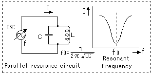
The coil and capacitor C on figure 2.6c form a parallel oscillatory circuit for "amplifying" a particular radio signal, while rejecting all other frequencies.
Fig. 2.6: a. Amplifier with headphones, b. Band-switch, c. Detector radio-receiver
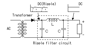
The most obvious application for a transformer is in a power supply. A typical transformer is shown in figure 3.8 and is used for converting 220V to 24V.
Fig. 3.8: Stabilized converter with circuit LM317
Output DC voltage can be adjusted via a linear potentiometer P, in 3~30V range.
Fig. 3.9: a. Stabilized converter with regulator 7806, b. auto-transformer, c. transformer for devices working at 110V, d. isolating transformer
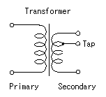
Figure 3.9a shows a simple power supply, using a transformer with a centre-tap on the secondary winding. This makes possible the use two diodes instead of the bridge in figure 3.8.
Special types of transformers, mainly used in laboratories, are auto-transformers. The diagram for an auto-transformer is shown in figure 3.9b. It features only one winding, wound on an iron core. Voltage is taken from the transformer via a slider. When the slider is in its lowest position, voltage equals zero. Moving the slider upwards increases the voltage U, to 220V. Further moving the slider increases the voltage U above 220V.
The transformer in figure 3.9c converts 220v to 110v and is used for supplying devices designed to work on 110V.
As a final example, figure 3.9d represents an isolating transformer. This transformer features the same number of turns on primary and secondary windings. Secondary voltage is the same as the primary, 220V, but is completely isolated from the "mains," minimizing the risks of electrical shock. As a result, a person can stand on a wet floor and touch any part of the secondary without risk, which is not the case with the normal power outlet.


 Coils are not a very common component in electronic circuits, however when they are used, they need to be understood. They are encountered in oscillators, radio-receivers, transmitter and similar devices containing oscillatory circuits. In amateur devices, coils can be made by winding one or more layers of insulated copper wire onto a former such as PVC, cardboard, etc. Factory-made coils come in different shapes and sizes, but the common feature for all is an insulated body with turns of copper wire.