About the circuit.
An audio level meter is a must in the workbench of an amplifier specialist and if it this audio level meter circuit then it will be more fine.You will like this because of its simplicity and of course effectiveness.
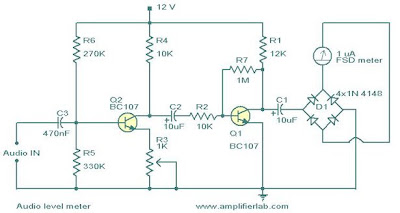
The circuit depicted here is designed to get a steady frequency response over the audio frequency range.The circuit has an input sensitivity of 100mV to get a full scale deflection on the meter.Two common emitter amplifiers form the heart of this circuit.The preset R3 in the first stage can be adjusted to get a full scale deflection on the meter.For getting maximum AC voltage deflection the second stage is kept biased at half the supply voltage.Capacitors C1,C2 and C3 act as filters.The diode bridge will covert the signal at the collector of Q1 to a varying DC voltage and this voltage will be proportional to the input signal level.The meter will show this voltage as reading.That’s all about the circuit.
Circuit diagram & Parts list.

Notes.
- This circuit will give only the instantaneous reading and peak readings will not be available.
- The calibration can be done in one step.Feed the input with a 1Khz 100mV peak to peak sine wave and adjust R3 to get a FSD on the meter.
- The circuit can be powered from a 12 V DC supply.I recommend a 12V battery for a noise free operation.
|
|


0 comments:
Post a Comment