Junction FET as an Amplifier Tutorial
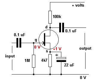
To correctly bias the fet, the gate needs to be negative with respect to the source.
Bias is obtained in the following manner.
Drain current flows through the source resistor and develops a voltage across it, making the emitter positive with respect the zero volts rail.
There is no gate current, so there is no current through the gate resistor.
This means that there is no voltage across this resistor, so it will be zero volts at both ends.
This means that there is zero volts on the gate .
Therefore the source is positive with respect to the gate.
The gate is negative with respect to the source.
The FET is biased correctly.
When a signal voltage is applied to the gate, it controls the drain current.
When the signal goes more negative (less positive) the drain current is reduced and the voltage across the drain resistor is less.
The drain voltage goes more positive.
When the signal goes less negative (more positive) the drain current is increased and the voltage across the drain resistor is more.
The drain voltage goes less positive.
|
|


0 comments:
Post a Comment