4. Transistors
Transistors are active components and are found everywhere in electronic circuits. They are used as amplifiers and switching devices. As amplifiers, they are used in high and low frequency stages, oscillators, modulators, detectors and in any circuit needing to perform a function. In digital circuits they are used as switches.
There is a large number of manufacturers around the world who produce semiconductors (transistors are members of this family of components), so there are literally thousands of different types. There are low, medium and high power transistors, for working with high and low frequencies, for working with very high current and/or high voltages. Several different transistors are shown on 4.1.
The most common type of transistor is called bipolar and these are divided into NPN and PNP types.
Their construction-material is most commonly silicon (their marking has the letter B) or germanium (their marking has the letter A). Original transistor were made from germanium, but they were very temperature-sensitive. Silicon transistors are much more temperature-tolerant and much cheaper to manufacture.

Fig. 4.1: Different transistors

Fig. 4.2: Transistor symbols: a - bipolar, b - FET, c - MOSFET, d - dual gate MOSFET,
e - inductive channel MOSFET, f - single connection transistor The second letter in transistor’s marking describes its primary use:
C - low and medium power LF transistor,
D - high power LF transistor,
F - low power HF transistor,
G - other transistors,
L - high power HF transistors,
P - photo transistor,
S - switch transistor,
U - high voltage transistor.
Here are few examples:
AC540 - germanium core, LF, low power,
AF125 - germanium core, HF, low power,
BC107 - silicon, LF, low power (0.3W),
BD675 - silicon, LF, high power (40W),
BF199 - silicon, HF (to 550 MHz),
BU208 - silicon (for voltages up to 700V),
BSY54 - silicon, switching transistor.
There is a possibility of a third letter (R and Q - microwave transistors, or X - switch transistor), but these letters vary from manufacturer to manufacturer.
The number following the letter is of no importance to users.
American transistor manufacturers have different marks, with a 2N prefix followed by a number (2N3055, for example). This mark is similar to diode marks, which have a 1N prefix (e.g. 1N4004).
Japanese bipolar transistor are prefixed with a: 2SA, 2SB, 2SC or 2SD, and FET-s with 3S:
2SA - PNP, HF transistors,
2SB - PNP, LF transistors,
2SC - NPN, HF transistors,
2SD - NPN, HF transistors.
Several different transistors are shown in photo 4.1, and symbols for schematics are on 4.2. Low power transistors are housed in a small plastic or metallic cases of various shapes. Bipolar transistors have three leads: for base (B), emitter (E), and for collector (C). Sometimes, HF transistors have another lead which is connected to the metal housing. This lead is connected to the ground of the circuit, to protect the transistor from possible external electrical interference. Four leads emerge from some other types, such as two-gate FETs. High power transistors are different from low-to-medium power, both in size and in shape.
It is important to have the manufacturer’s catalog or a datasheet to know which lead is connected to what part of the transistor. These documents hold the information about the component's correct use (maximum current rating, power, amplification, etc.) as well as a diagram of the pinout. Placement of leads and different housing types for some commonly used transistors are in diagram 4.3.

Fig. 4.3: Pinouts of some common packages
It might be useful to remember the pinout for TO-1, TO-5, TO-18 and TO-72 packages and compare them with the drawing 4.2 (a). These transistors are the ones you will come across frequently in everyday work.
The TO-3 package, which is used to house high-power transistors, has only two pins, one for base, and one for emitter. The collector is connected to the package, and this is connected to the rest of the circuit via one of the screws which fasten the transistor to the heat-sink.
Transistors used with very high frequencies (like BFR14) have pins shaped differently.
One of the breakthroughs in the field of electronic components was the invention of SMD (surface mount devices) circuits. This technology allowed manufacturers to achieve tiny components with the same properties as their larger counterparts, and therefore reduce the size and cost of the design. One of the SMD housings is the SOT23 package. There is, however, a trade-off to this, SMD components are difficult to solder to the PC board and they usually need special soldering equipment.
As we said, there are literally thousands of different transistors, many of them have similar characteristics, which makes it possible to replace a faulty transistor with a different one. The characteristics and similarities can be found in comparison charts. If you do not have one these charts, you can try some of the transistors you already have. If the circuit continues to operate correctly, everything is ok. You can only replace an NPN transistor with an NPN transistor. The same goes if the transistor is PNP or a FET. It is also necessary to make sure the pinout is correct, before you solder it in place and power up the project.
As a helpful guide, there is a chart in this chapter which shows a list of replacements for some frequently used transistors.
4.1 The working principle of a transistor
Transistors are used in analog circuits to amplify a signal. They are also used in power supplies as a regulator and you will also find them used as a switch in digital circuits.
The best way to explore the basics of transistors is by experimenting. A simple circuit is shown below. It uses a power transistor to illuminate a globe. You will also need a battery, a small light bulb (taken from a flashlight) with properties near 4.5V/0.3A, a linear potentiometer (5k) and a 470 ohm resistor. These components should be connected as shown in figure 4.4a.

Fig. 4.4: Working principle of a transistor: potentiometer moves toward its upper position - voltage on the base increases - current through the base increases - current through the collector increases - the brightness of the globe increases.
Resistor (R) isn't really necessary, but if you don't use it, you mustn't turn the potentiometer (pot) to its high position, because that would destroy the transistor - this is because the DC voltage UBE (voltage between the base and the emitter), should not be higher than 0.6V, for silicon transistors.
Turn the potentiometer to its lowest position. This brings the voltage on the base (or more correctly between the base and ground) to zero volts (UBE = 0). The bulb doesn't light, which means there is no current passing through the transistor.
As we already mentioned, the potentiometers lowest position means that UBE is equal to zero. When we turn the knob from its lowest position UBE gradually increases. When UBE reaches 0.6v, current starts to enter the transistor and the globe starts to glow. As the pot is turned further, the voltage on the base remains at 0.6v but the current increases and this increases the current through the collector-emitter circuit. If the pot is turned fully, the base voltage will increase slightly to about 0.75v but the current will increase significantly and the globe will glow brightly.
If we connected an ammeter between the collector and the bulb (to measure IC), another ammeter between the pot and the base (for measuring IB), and a voltmeter between the ground and the base and repeat the whole experiment, we will find some interesting data. When the pot is in its low position UBE is equal to 0V, as well as currents IC and IB. When the pot is turned, these values start to rise until the bulb starts to glow when they are: UBE = 0.6V, IB = 0.8mA and IB = 36 mA (if your values differ from these values, it is because the 2N3055 the writer used doesn't have the same specifications as the one you use, which is common when working with transistors).
The end result we get from this experiment is that when the current on the base is changed, current on the collector is changed as well.
Let's look at another experiment which will broaden our knowledge of the transistor. It requires a BC107 transistor (or any similar low power transistor), supply source (same as in previous experiment), 1M resistor, headphones and an electrolytic capacitor whose value may range between 10u to 100µF with any operating voltage.
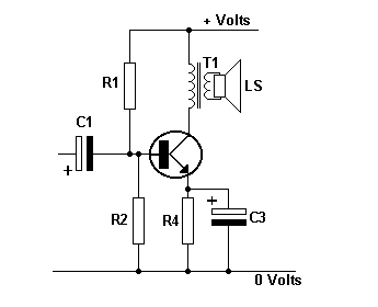
A simple low frequency amplifier can be built from these components as shown in diagram 4.5.

Fig. 4.5: A simple transistor amplifier
It should be noted that the schematic 4.5a is similar to the one on 4.4a. The main difference is that the collector is connected to headphones. The "turn-on" resistor - the resistor on the base, is 1M. When there is no resistor, there is no current flow IB, and no Ic current. When the resistor is connected to the circuit, base voltage is equal to 0.6V, and the base current IB = 4µA. The transistor has a gain of 250 and this means the collector current will be 1 mA. Since both of these currents enter the transistor, it is obvious that the emitter current is equal to IE = IC + IB. And since the base current is in most cases insignificant compared to the collector current, it is considered that:
The relationship between the current flowing through the collector and the current flowing through the base is called the transistor's current amplification coefficient, and is marked as hFE. In our example, this coefficient is equal to:

Put the headphones on and place a fingertip on point 1. You will hear a noise. You body picks up the 50Hz AC "mains" voltage. The noise heard from the headphones is that voltage, only amplified by the transistor. Let's explain this circuit a bit more. Ac voltage with frequency 50Hz is connected to transistor's base via the capacitor C. Voltage on the base is now equal to the sum of a DC voltage (0.6 approx.) via resistor R, and AC voltage "from" the finger. This means that this base voltage is higher than 0.6V, fifty times per second, and fifty times slightly lower than that. Because of this, current on the collector is higher than 1mA fifty times per second, and fifty times lower. This variable current is used to shift the membrane of the speakerphones forward fifty times per second and fifty times backwards, meaning that we can hear the 50Hz tone on the output.
Listening to a 50Hz noise is not very interesting, so you could connect to points 1 and 2 some low frequency signal source (CD player or a microphone).
There are literally thousands of different circuits using a transistor as an active, amplifying device. And all these transistors operate in a manner shown in our experiments, which means that by building this example, you're actually building a basic building block of electronics.
4.2 Basic characteristics of transistors
Selecting the correct transistor for a circuit is based on the following characteristics: maximum voltage rating between the collector and the emitter UCEmax, maximum collector current ICmax and the maximum power rating PCmax.
If you need to change a faulty transistor, or you feel comfortable enough to build a new circuit, pay attention to these three values. Your circuit must not exceed the maximum rating values of the transistor. If this is disregarded there are possibilities of permanent circuit damage. Beside the values we mentioned, it is sometimes important to know the current amplification, and maximum frequency of operation.
When there is a DC voltage UCE between the collector (C) and emitter (E) with a collector current, the transistor acts as a small electrical heater whose power is given with this equation:

Because of that, the transistor is heating itself and everything in its proximity. When UCE or ICE rise (or both of them), the transistor may overheat and become damaged. Maximum power rating for a transistor, is PCmax (found in a datasheet). What this means is that the product of UCE and IC should should not be higher than PCmax:
So, if the voltage across the transistor is increased, the current must be dropped.
For example, maximum ratings for a BC107 transistor are:
ICmax=100mA,
UCEmax = 45V and
PCmax = 300mW
If we need a Ic=60mA , the maximum voltage is:
For UCE = 30V, the maximum current is:

Among its other characteristics, this transistor has current amplification coefficient in range between hFE= 100 to 450, and it can be used for frequencies under 300MHz. According to the recommended values given by the manufacturer, optimum results (stability, low distortion and noise, high gain, etc.) are with UCE=5V and IC=2mA.
There are occasions when the heat generated by a transistor cannot be overcome by adjusting voltages and current. In this case the transistors have a metal plate with hole, which is used to attach it to a heat-sink to allow the heat to be passed to a larger surface.
Current amplification is of importance when used in some circuits, where there is a need for equal amplification of two transistors. For example, 2N3055H transistors have hFE within range between 20 and 70, which means that there is a possibility that one of them has 20 and other 70. This means that in cases when two identical coefficients are needed, they should be measured. Some multimeters have the option for measuring this, but most don't. Because of this we have provided a simple circuit (4.6) for testing transistors. All you need is an option on your multimeter for measuring DC current up to 5mA. Both diodes (1N4001, or similar general purpose silicon diodes) and 1k resistors are used to protect the instrument if the transistor is "damaged". As we said, current gain is equal to hFE = IC / IB. In the circuit, when the switch S is pressed, current flows through the base and is approximately equal to IB=10uA, so if the collector current is displayed in milliamps. The gain is equal to:

For example, if the multimeter shows 2.4mA, hFE = 2.4*100 = 240.
Fig. 4.6: Measuring the hFE
While measuring NPN transistors, the supply should be connected as shown in the diagram. For PNP transistors the battery is reversed. In that case, probes should be reversed as well if you're using analog instrument (one with a needle). If you are using a digital meter (highly recommended) it doesn't matter which probe goes where, but if you do it the same way as you did with NPN there would be a minus in front of the read value, which means that current flows in the opposite direction.
4.3 The safest way to test transistors
Another way to test transistor is to put it into a circuit and detect the operation. The following circuit is a multivibrator. The "test transistor" is T2. The supply voltage can be up to 12v. The LED will blink when a good transistor is fitted to the circuit.
Fig. 4.7: Oscillator to test transistors
To test PNP transistors, same would go, only the transistor which would need to be replaced is the T1, and the battery, LED, C1 and C2 should be reversed.
4.4 TUN and TUP
As we previously said, many electronic devices work perfectly even if the transistor is replaced with a similar device. Because of this, many magazines use the identification TUN and TUP in their schematics. These are general purpose transistors. TUN identifies a general purpose NPN transistor, and TUP is a general purpose PNP transistor.
TUN = Transistor Universal NPN and TUP = Transistor Universal PNP.
These transistors have following characteristics:
4.5 Practical example
The most common role of a transistor in an analog circuit is as an active (amplifying) component. Diagram 4.8 shows a simple radio receiver - commonly called a "Crystal Set with amplifier."
Variable capacitor C and coil L form a parallel oscillating circuit which is used to pick out the signal of a radio station out of many different signals of different frequencies. A diode, 100pF capacitor and a 470k resistor form a diode detector which is used to transform the low frequency voltage into information (music, speech). Information across the 470k resistor passes through a 1uF capacitor to the base of a transistor. The transistor and its associated components create a low frequency amplifier which amplifies the signal.
On figure 4.8 there are symbols for a common ground and grounding. Beginners usually assume these two are the same which is a mistake. On the circuit board the common ground is a copper track whose size is significantly wider than the other tracks. When this radio receiver is built on a circuit board, common ground is a copper strip connecting holes where the lower end of the capacitor C, coil L 100pF capacitor and 470k resistor are soldered. On the other hand, grounding is a metal rod stuck in a wet earth (connecting your circuits grounding point to the plumbing or heating system of your house is also a good way to ground your project).
Resistor R2 biases the transistor. This voltage should be around 0.7V, so that voltage on the collector is approximately equal to half the battery voltage.

Fig. 4.8: Detector receiver with a simple amplifier
Web site
tags: Transistors, amplifier, components, digital, mosfet


 Step 2 - FINDING THE COLLECTOR and EMITTER
 For a PNP transistor, set the meter to "x10k" place the leads on the transistor and when you press hard on the two leads shown in the diagram below, the needle will swing almost full scale.