Showing posts with label Electronics Basics. Show all posts

Wednesday, February 29, 2012

Explaining solar cells

|2 comments
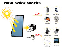
As renewable energy is becoming integrated into our everyday lives, new terms such as solar panel, photovoltaic and solar cell are more common and new devices, such as outdoor LED lighting are using this technology. The sun emits many forms of radiation. The best way to describe this is that there are ‘waves’ of energy that radiate from the sun at different frequencies.
This is only partially the truth as there is both a wave and particle nature to light.
The light spectrum is divided into different sections. It begins with the highest, gamma rays and ends with the lowest, long wave radio. Only a small portion of this is visible, called the visible spectrum and this occurs towards the middle of the range which lies between Ultraviolet and Infrared frequencies. Ultraviolet radiation is what burns the skin and can cause skin cancer. It is blocked by most types of glass and is partially reduced by the atmosphere especially the ozone layer. Infrared radiation is what provides the earth with heat and it is that which is trapped by green house gasses, carbon dioxide mainly and is causing global warming.
Infrared radiation is targeted by solar panels. This basically uses the energy generated by the radiation to heat water in pipes that flows and generates electricity. This can be used to charge a battery which could then power said LED lighting. As mentioned previously there is a dual nature to light. It consists of both a particle and a wave. It might help to think of the particles moving in a wave like pattern but the reality is more complex than that. The important thing to remember is that the light particle, the photon, is what is targeted by a solar cell.
Generally speaking the solar cell works by providing energy to a semiconducting material, most commonly silicon, so that electrons within the material are released from the bonds to their atoms in the semiconductor.
The arrangement of the cell into strips of conductor and semiconductor allow these freed electrons to move. They move in a directed manner away from the incoming energy, the photons, creating a flow of electrons more commonly known as current.
A high incoming rate of photons is required to release the electrons. This creates problems as much of the higher energy (higher frequency) waves emitted by the sun are blocked; the glass protective covering reflects light requiring anti-reflection membranes, glass blocks ultraviolet and the lower range of frequencies like infrared do not have enough energy to have much of an effect on the panels. Thus these panels only really target the visible spectrum which is only a small proportion of the sun’s energy.
Yet, with the improvements to the semiconductors, the anti reflection layers and the methods of directing the released electrons the efficiency of solar cells has dramatically improved. Huge fields of cells are being created in deserts and mountainous regions that can now produce kilowatts of energy.
Combined with the improvements of energy efficient products, such as LED lighting, this is becoming a valuable resource. In fact, the low energy of LED lighting is one of the most important improvements as it helps to alleviate the greatest weakness of solar cells – night time.
source: electronics-lab
Tags: cells, Led, Photovoltaics, Solar 

Sunday, February 26, 2012

testing an unknown transistor

|0 comments
TESTING AN unknown TRANSISTOR

The first thing you may want to do is test an unknown transistor for COLLECTOR, BASE AND EMITTER. You also need to know if it is NPN or PNP.
You need a cheap multimeter called an ANALOGUE METER  - a multimeter with a scale and pointer (needle).
It will measure resistance values (normally used to test resistors) - (you can also test other components) and Voltage and Current. We use the resistance settings. It may have ranges such as "x10"  "x100"   "x1k"   "x10"
Look at the resistance scale on the meter. It will be the top scale.
The scale starts at zero on the right and the high values are on the left. This is opposite to all the other scales. .
When the two probes are touched together, the needle swings FULL SCALE and reads "ZERO." Adjust the pot on the side of the meter to make the pointer read exactly zero.

How to read:  "x10"  "x100"   "x1k"   "x10"
Up-scale from the zero mark is "1" 
When the needle swings to this position on the "x10" setting, the value is 10 ohms.
When the needle swings to "1" on the "x100" setting, the value is 100 ohms.
When the needle swings to "1" on the "x1k" setting, the value is 1,000 ohms = 1k.
When the needle swings to "1" on the "x10k" setting, the value is 10,000 ohms = 10k.
Use this to work out all the other values on the scale.
Resistance values get very close-together (and very inaccurate) at the high end of the scale. [This is just a point to note and does not affect testing a transistor.]
Step 1   - FINDING THE BASE  and determining NPN or PNP
Get an unknown transistor and test it with a multimeter set to "x10"
Try the 6 combinations and when you have the black probe on a pin and the red probe touches the other pins and the meter swings nearly full scale, you have an NPN transistor. The black probe is BASE
If the red probe touches a pin and the black probe produces a swing on the other two pins, you have a PNP transistor. The red probe is BASE
If the needle swings FULL SCALE or if it swings for more than 2 readings, the transistor is FAULTY
Step 2   - FINDING THE COLLECTOR and EMITTER
Set the meter to "x10k." 
For an NPN transistor, place the leads on the transistor and when you press hard on the two leads shown in the diagram below, the needle will swing almost full scale.   


For a PNP transistor, set the meter to "x10k"  place the leads on the transistor and when you press hard on the two leads shown in the diagram below, the needle will swing almost full scale.   


Thursday, February 23, 2012

What is Solar Power?

|1 comments
what is solar energy?

Solar power is energy generated from the heat or light from the sun which can be used to produce heat, light, hot water, electricity, and cooling in a wide variety of applications .  When we say something is solar powered, we mean that the energy it uses was converted directly from solar energy or sunlight energy. Solar energy is often referred to as an "alternative energy" to fossil fuel energy sources such as oil and coal.

The history of photovoltaic technology

We've used the Sun for drying clothes and food for thousands of years, but only recently have we been able to use it for generating power.
The history of photovoltaic technology goes back more than one hundred years but it wasn't until the middle of the 20th century that scientists at Bell Telephone found that an element called silicon produced an electrical charge when exposed to sunlight. However, the earliest solar cells were expensive and not very efficient, converting only a fraction of the sun's light into electric current. Today, solar panel technology has vastly improved efficiency.

What is solar power offering that makes it such an appealing energy source?

•Solar energy is a completely free and inexhaustible fuel source
•No fuel, waste, or pollution is expelled in its usage.
•In remote areas, or small villages, solar power can be the saving grace. Sometimes it is the only realistic way to provide energy to a place that is not capable of drawing energy from other sources.
•It can be used for low-power purposes as well as larger ones- from battery chargers, hand-held calculators, and solar powered garden lights to air conditioning, cars, and satellites.

Solar energy can be an integral part of any combination of clean, renewable energy sources to meet the nation's need for electricity while reducing harmful greenhouse gas emissions.
tags: solar power, solar panels, solar power systems, home solar energy, solar cell

Light Emitting Diode Part IV

|0 comments
THE RESISTOR
The value of the current limiting resistor can be worked out by Ohms Law.
Here are the 3 steps:
1. Add up the voltages of all the LEDs in a string.   e.g:  2.1v + 2.3v + 2.3v + 1.7v = 8.4v
2. Subtract the LED voltages from the supply voltage.  e.g:  12v - 8.4v = 3.6v
3. Divide the 3.6v (or your voltage) by the current through the string. 
for 25mA:   3.6/.025 =144 ohms
for 20mA:   3.6/.02  = 180 ohms
for 15mA:   3.6/.015 = 250 ohms
for 10mA:   3.6/.01   = 360 ohms
This is the value of the current-limiting resistor.

Here is a set of strings for a supply voltage of 3v to 12v and a single LED:

Here is a set of strings for a supply voltage of 5v to 12v and a white LED: 
Here is a set of strings for a supply voltage of 5v to 12v and two LEDs:

Light Emitting Diode Part III

|0 comments
LEDs ARE CURRENT DRIVEN DEVICES
A LED is described as a CURRENT DRIVEN DEVICE.  This means the illumination is determined by the amount of current flowing through it.
The brightness of a LED can be altered by increasing or decreasing the current. The effect will not be linear and it is best to experiment to determine the best current-flow for the amount of illumination you want. High-bright LEDs and super-bright LEDs will illuminate at 1mA or less, so the quality of a LED has a lot to do with the brightness. The life of many LEDs is determined at 17mA. This seems to be the best value for many types of LEDs.

1mA to 5mA LEDs
Some LEDs will produce illumination at 1mA. These are "high Quality" or "High Brightness" LEDs and the only way to check this feature is to test them @1mA as shown below. 

THE 5v LED 
Some suppliers and some websites talk about a 5v white or blue LED. Some LEDs have a small internal resistor and can be placed on a 5v supply. This is very rate.
Some websites suggest placing a white LED on a 5v supply. These LEDs have a characteristic voltage-drop of 3.6v and should not be placed directly on a voltage above this value.
The only LED with an internal resistor is a FLASHING LED. These LEDs can be placed on a supply from 5v to 12v and flash at approx 2Hz.
NEVER assume a LED has an internal resistor. Always add a series resistor. Some high intensity LEDs are designed for 12v operation. These LEDs have a complete internal circuit to deliver the correct current to the LED. This type of device is not covered in this eBook.

LEDs IN SERIES
LEDs can be placed in series providing some features are taken into account. The main item to include is a current-limiting resistor.
A LED and resistor is called a string. A string can have 1, 2, 3 or more LEDs.
Three things must be observed:
1. MAXIMUM CURRENT through each string = 25mA.
2. The CHARACTERISTIC VOLTAGE-DROP must be known so the correct number of LEDs are used in any string.
3. A DROPPER RESISTOR must be included for each string.
The following diagrams show examples of 1-string, 2-strings and 3-strings: 

LEDs IN PARALLEL
LEDs CANNOT be placed in parallel - until you read this:
LEDs "generate" or "possess" or "create" a voltage across them called the
CHARACTERISTIC VOLTAGE-DROP  (when they are correctly placed in a circuit).
This voltage is generated by the type of crystal and is different for each colour as well as the "quality" of the LED (such as high-bright, ultra high-bright etc). This characteristic cannot be altered BUT it does change a very small amount from one LED to another in the same batch. And it does increase slightly as the current increases.
For instance, it will be different by as much as 0.2v for red LEDs and 0.4v for white LEDs from the same batch and will increase by as much as 0.5v when the current is increased from a minimum to maximum.
You can test 100 white LEDs @15mA and measure the CHARACTERISTIC VOLTAGE-DROP to see this range.
If you get 2 LEDs with identical
CHARACTERISTIC VOLTAGE-DROP, and place them in parallel, they will each take the same current. This means 30mA through the current-limiting resistor will be divided into 15mA for each LED.
However if one LED has a higher
CHARACTERISTIC VOLTAGE-DROP, it will take less current and the other LED will take considerably more. Thus you have no way to determine the "current-sharing"  in a string of parallel LEDs.  If you put 3 or more LEDs in parallel, one LED will start to take more current and will over-heat and you will get very-rapid LED failure.  As one LED fails, the others will take more current and the rest of the LEDs will start to self-destruct.
Thus LEDs in PARALLEL should be avoided.
Diagram A below shows two green LEDs in parallel. This will work provided the Characteristic Voltage Drop across each LED is the same.
In diagram B the Characteristic Voltage Drop is slightly different for the second LED and the first green LED will glow brighter.
In diagram C the three LEDs have different Characteristic Voltage Drops and the red LED will glow very bright while the other two LEDs will not illuminate. All the current will pass through the red LED and it will be damaged.
The reason why the red LED will glow very bright is this: It has the lowest Characteristic Voltage Drop and it will create a 1.7v for the three LEDs. The green and orange LEDs will not illuminate at this voltage and thus all the current
from the dropper resistor will flow in the red LED and it will be destroyed.

 Part I ... Part II ... Part III ... Part IV

tags: devices, led parallel circuit, voltage

Light Emitting Diode Part II

|0 comments

The voltage dropped across this resistor, combined with the current, constitutes wasted energy and should be kept to a minimum, but a small HEAD VOLTAGE is not advisable (such as 0.5v). The head voltage should be a minimum of 1.5v - and this only applies if the supply is fixed.
The head voltage depends on the supply voltage. If the supply is fixed and guaranteed not to increase or fall, the head voltage can be small (1.5v minimum).
But most supplies are derived from batteries and the voltage will drop as the cells are used.
Here is an example of a problem:
Supply voltage:  12v
7  red LEDs in series = 11.9v
Dropper resistor = 0.1v
As soon as the supply drops to 11.8v, no LEDs will be illuminated.
Example 2:
Supply voltage 12v
5 green LEDs in series @ 2.1v = 10.5v
Dropper resistor = 1.5v
The battery voltage can drop to 10.5v
But let's look at the situation more closely.
Suppose the current @ 12v = 25mA.
As the voltage drops, the current will drop.
At 11.5v, the current will be 17mA
At 11v, the current will be 9mA
At 10.5v, the current will be zero
You can see the workable supply drop is only about 1v.
Many batteries drop 1v and still have over 80% of their energy remaining. That's why you need to design your circuit to have a large
HEAD VOLTAGE.

TESTING A LED 
If the cathode lead of a LED cannot be identified, place 3 cells in series with a 220R resistor and illuminate the LED.  4.5v allows all types of LEDs to be tested as white LEDs require up to 3.6v.  Do not use a multimeter as some only have one or two cells and this will not illuminate all types of LEDs. In addition, the negative lead of a multimeter is connected to the positive of the cells (inside the meter) for resistance measurements - so you will get an incorrect determination of the cathode lead. 


CIRCUIT TO TEST ALL TYPES OF LEDs

IDENTIFYING A LED
 A LED does not have a "Positive" or "Negative" lead. It has a lead identified as the "Cathode" or Kathode" or "k". This is identified by a flat on the side of the LED and/or by the shortest lead.
This lead goes to the 0v rail of the circuit or near the 0v rail (if the LED is connected to other components).
Many LEDs have a "flat" on one side and this identifies the cathode. Some surface-mount LEDs have a dot or shape to identify the cathode lead and some have a cut-out on one end.
Here are some of the identification marks:  

 
 Part I ... Part II ... Part III ... Part IV
tags:  voltage, battery voltage

Light Emitting Diode

|0 comments

CONNECTING A LED
A LED must be connected around the correct way in a circuit and it must have a resistor to limit the current.
The LED in the first diagram does not illuminate because a red LED requires 1.7v and the cell only supplies 1.5v. The LED in the second diagram is damaged because it requires 1.7v and the two cells supply 3v. A resistor is needed to limit the current to about 25mA and also the voltage to 1.7v, as shown in the third diagram.  The fourth diagram is the circuit for layout #3 showing the symbol for the LED, resistor and battery and how the three are connected. The LED in the fifth diagram does not work because it is around the wrong way.  

CHARACTERISTIC VOLTAGE DROP
When a LED is connected around the correct way in a circuit it develops a voltage across it called the CHARACTERISTIC VOLTAGE DROP.
A LED must be supplied with a voltage that is higher than its "CHARACTERISTIC VOLTAGE" via a resistor - called a VOLTAGE DROPPING RESISTOR  or CURRENT LIMITING RESISTOR - so the LED will operate correctly and provide at least 10,000 to 50,000 hours of illumination.
A LED works like this:  A LED and resistor are placed in series and connected to a voltage.
As the voltage rises from 0v, nothing happens until the voltage reaches about 1.7v. At this voltage a red LED just starts to glow. As the voltage increases, the voltage across the LED remains at 1.7v but the current through the LED increases and it gets brighter.
We now turn our attention to the current though the LED.  As the current increases to 5mA, 10mA, 15mA, 20mA the brightness will increase and at 25mA, it will be a maximum. Increasing the supply voltage will simply change the colour of the LED slightly but the crystal inside the LED will start to overheat and this will reduce the life considerably.
This is just a simple example as each LED has a different CHARACTERISTIC VOLTAGE DROP and a different maximum current.
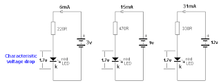
In the diagram below we see a LED on a 3v supply, 9v supply and 12v supply. The current-limiting resistors are different and the first circuit takes 6mA, the second takes 15mA and the third takes 31mA. But the voltage across the red LED is the same in all cases. This is because the LED creates the
CHARACTERISTIC VOLTAGE DROP and this does not change. 

It does not matter if the resistor is connected above or below the LED. The circuits are the SAME in operation:
HEAD VOLTAGE
Now we turn our attention to the resistor.
As the supply-voltage increases, the voltage across the LED will be constant at 1.7v (for a red LED) and the excess voltage will be dropped across the resistor. The supply can be any voltage from 2v to 12v or more.
In this case, the resistor will drop 0.3v to 10.3v.
This is called HEAD VOLTAGE - or HEAD-ROOM or OVERHEAD-VOLTAGE.
The following diagram shows HEAD VOLTAGE:

 Part I ... Part II ... Part III ... Part IV
tags:  Light Emitting Diode, diode, led power supplies

Monday, January 10, 2011

DC Voltmeters

|0 comments

DC voltmeter mainly consists of a dc ampli­fier apart from the attenuator, as shown in figure.
DC Voltmeter Block Diagram
DC voltmeters can further be divided into two categories.

1. Direct Coupled Amplifier DC Voltmeter. 

DC Voltmeter

 This type of voltmeter is very common because of its low cost. This instrument can be used only to measure voltages of the order of milli-volts owing to limited amplifier gain. The circuit diagram for a direct coupled am­plifier dc voltmeter using cascaded transistors is shown in figure. An attenuator is used in input stage to select voltage range. A transistor is a current controlled device so resistance is inserted in series with the transistor Q1 to select the voltage range. It can be seen from figure that sensitivity of voltmeter is 200 kilo ohms/volt neglecting small resistance offered by transistor Q1. Other values of range selecting resistors are also so chosen that sensitivity remains the same for all ranges. So current drawn from the circuit is only 5micro Ampere.

Two transistors in cascaded connections are used instead of using a single transistor for amplification in order to keep the sensitivity of the circuit high. Transistors Q1 and Q2 are taken complement to each other and are directly coupled to minimize the number of components in the circuit. They form a direct coupled amplifier. A variable resistance R is put in the circuit for zero adjustment of the PMMC. It controls the bucking current from the supply E to buck out the quiescent current. The draw-back of such a voltmeter is that it has to work under specified ambient temperature to get the required accuracy otherwise excessive drift problem occurs during operation.
DC Voltmeter using FET
Another circuit diagram of a direct coupled amplifier dc voltmeter using FET in input stage is shown in figure. In this voltmeter, voltage to be measured is firstly attenuated with range selector switch to keep the input voltage of amplifier within its level. FET is used in the input stage of amplifier because of its high input impedance so that is does not load the circuit of which voltage is to be measured and it also keeps the sensitivity of voltmeter very high. As FET is a voltage controlled device so resistance network of attenuator is put in shunt in the circuit. Transistors Q2 and Q3 form the direct coupled dc amplifier whose output is finally supplied to PMMC meter. When transistors work within their dynamic region, the deflec­tion of meter remains proportional to the applied input voltage. This voltmeter can be used for measurement of voltages of the order of milli-volts because of sufficient gain of ampli­fier.
Apart from the high input imped­ance, this circuit has another advan­tage that when in­put voltage exceeds its limit, amplifier gets saturated which limits the current passing through the PMMC meter. So meter does not burn out.

2.     Chopper Type DC Voltme­ter.

Chopper Type DC Voltmeter

 Chopper type dc amplifier is used in highly sensitive dc electronic  volt­meters. Its block diagram is shown in figure. Firstly dc input voltage is converted into ac voltage by chopper modulator and then it is supplied to an ac amplifier,   i Output of am­plifier is then demodulated to a dc voltage proportional to the original input voltage. Modulator chopper and demodulator chopper act in anti-synchronism.Chopper system may be either mechanical or electronic.

Chopper Type DC Voltmete
Circuit diagram of an electronic chopper employing photo diodes is shown in figure. Photo diodes change its resistance under different illumination conditions, this property f photo diode is used in chopper amplifier. Its resistance changes from the order of few mega-ohms to few hundred ohms when it is illuminated by a light source in the dark place.
Two neon lamps are used in this circuit, these are supplied by an oscillator for alter­nate half cycles. Two photo diodes are used in input stage which acts as half-wave modu­lators because of its alternate switching action by the neon lamps at the frequency of oscillator.
Output of chopper modulator is a square wave voltage (proportional to the input signal) which is supplied to the ac amplifier through a capacitor. Amplified output is again passed through a capacitor and then fed to chopper demodulator. Capacitor is used to remove dc drift from the signal. Chopper demodulator gives a dc output voltage (proportional to the input voltage) which is passed through the low pass filter to remove any residual ac component. Now this dc output voltage is supplied to the PMMC meter for measurement of input voltage.
In chopper amplifier dc voltmeter, input impedance is of the order of hundred mega-ohms and it has sensitivity of one micro-volt per scale division.

Thursday, October 1, 2009

Digital vs. Analog Volume Control

|0 comments
Digital vs. Analog Volume Control

Digital vs. Analog Volume Control

The volume control in digital processors (or CD players) can be implemented in the analog or the digital domain. That is, the analog signal can be put through a standard volume-control knob as is found on a preamplifier, or the volume can be adjusted by performing mathematical operations on the digital data representing the music. Before deciding a digital processor with volume control, you should know the tradeoffs inherent in each approach.

An analog volume control can slightly degrade the signal - no volume control is perfectly transparent - and can introduce small channel balance errors at certain volume settings. For example, when the volume is turned very low, the left channel may be half a dB louder than the right. This situation could reverse as the volume is turned up.

A digital volume control has its own problems. Each 6dB reduction in volume from the maximum setting throws away one bit of resolution. A low volume setting (say, 30dB of attenuation) is equivalent to discarding five bits. If you had true 20-bit resolution in your D/A converter, you'd be listening to 15-bit audio instead of 20-bit. The lower the volume setting, the greater the loss in resolution.

Digital volume control such as DS1669 from Dallas Semiconductor is actually easier and cheaper to implement than analog volume control. Most digital filters have a volume control built-in; the designer need only send a control code to the filter chip to adjust the volume. An analog control requires a potentiometer (the volume control itself), another hole in the chassis, and wiring between the circuit board and potentiometer.
Source: Digital vs. Analog Volume Control

Thursday, September 3, 2009

Voltage Follower Circuit

|0 comments

Two examples of the most common types of Voltage followers (buffers). You can find some theory behind them in our amplifier gain and buffer amplifier pages.

Transistor voltage follower:

This first circuit is a very simple one transistor voltage follower. Consist of two biasing resistors, and one other resistor at the emitter to acquire the output voltage from.

How it works:

The first to resistors connected to the transistor's base are forming a voltage divider, in order to set a biasing point for the transistor to work in our desired range. Then the transistor, our gain component for the circuit which in this case is only used as a gateway to isolate two circuit stages.

The resistor in the emitter is used to create a voltage from the current passing from the transistor; Without it we can't get any voltage as our output would be effectively shorted to ground (0 volts).

The capacitors that are displayed in the schematic are optional, but very useful to prevent a wrong operation of the circuit, specially in audio or high frequency uses. they stop any DC voltage to move or otherwise disrupt the bias point of the transistor, thus causing undesired operation. If you build this circuit only with dc remove the capacitors, as they will prevent the circuit from functioning under those conditions.

Transistor voltage follower


Op Amp Voltage Follower:

This circuit's operation is far more predictable and stable than the transistor version, and also requires less external components.

How it works:

Works as described above, no external elements to explain. This circuit uses feedback to maintain the voltage output the same as the input. Note that this schematic does not display power, ground and other connections for the op amp, these vary widely among manufacturers and op amps so refer to your op amp's datasheet for pinouts and power connections.
Opamp voltage follower
Source: Electronic Circuits For Beginners

Monday, August 10, 2009

Using Electret Condenser Microphones

|0 comments

Description:
This page describes how to use or connect and use 2 and 3 terminal electret condenser microphones (ECM's). The bottom section shows the connections and how to substitute from one type to another.


Mic Inserts
Viewed from above all mic inserts look similar to the left image. ECM inserts can be bought quite cheaply from many electronics outlets, and offer high quality sound output. They can also be salvaged from old cassette players and radio-casettes. An ECM contains a very sensitive electret type microphone (high output impedance) and an integral FET amplifier. The amplifier stage buffers the high output impedance of the mic and boosts an average speech signal to around 1 to 2mV when spoken about one metre away from the mic insert.


Two Terminal Type ECM The ground or common connection of a two terminal ECM insert can be identified as the solder connection that is touching the case or body of the mic, see right.


Three Terminal Type ECM
With a three terminal ECM, the ground or common connection will be touching the case or body, the other two contacts will be the audio output and power pins, see below.


Connecting 2 and 3 terminal ECM's


The schematic symbol for a 3 terminal ECM insert is shown on the left diagram. It has separate power, common, and signal outputs. The schematic symbol for a 2 terminal ECM insert is shown on the right diagram. To use a 2 terminal ECM, the signal output is connected to the power terminal, fed via a current limiting resistor, (typical value 1k or 2k2). The signal output therefore has a DC component which must be removed before connecting to an amplifier. This is acheived with an output capacitor connected to the power terminal of the ECM, a typical value being 1-10uF.
Source : http://www.zen22142.zen.co.uk

Wednesday, July 29, 2009

Bridge rectifiers

|0 comments
There are several ways of connecting diodes to make a rectifier to convert AC to DC. The bridge rectifier is one of them and it is available in special packages containing the four diodes required. Bridge rectifiers are rated by their maximum current and maximum reverse voltage. They have four leads or terminals: the two DC outputs are labeled + and -, the two AC inputs are labeled


Bridge rectifier


Example: Circuit symbol:

Function


Diodes allow electricity to flow in only one direction. The arrow of the circuit symbol shows the
direction in which the current can flow. Diodes are the electrical version of a valve and early diodes were actually called valves.


Forward Voltage Drop

Electricity uses up a little energy pushing its way through the diode, rather like a person pushing through a door with a spring. This means that there is a small voltage across a conducting diode, it is called the forward voltage drop and is about 0.7V for all normal diodes which are made from silicon. The forward voltage drop of a diode is almost constant whatever the current passing through the diode so they have a very steep characteristic (current-voltage graph).

Reverse Voltage

When a reverse voltage is applied a perfect diode does not conduct, but all real diodes leak a very tiny current of a few µA or less. This can be ignored in most circuits because it will be very much smaller than the current flowing in the forward direction. However, all diodes have a maximum reverse voltage (usually 50V or more) and if this is exceeded the diode will fail and pass a large current in the reverse direction, this is called breakdown.

Signal diodes (small current)

Signal diodes are used to process information (electrical signals) in circuits, so they are only required to pass small currents of up to 100mA.
General purpose signal diodes such as the 1N4148 are made from silicon and have a forward voltage drop of 0.7V.

Source : http://robosapienv2-4mem8.page.tl

Relays

|0 comments
A relay is an electrically operated switch. Current flowing through the coil of the relay creates a magnetic field which attracts a lever and changes the switch contacts. The coil current can be on or off so relays have two switch positions and they are double throw (changeover) switches.

Relays allow one circuit to switch a second circuit which can be completely separate from the first. For example a low voltage battery circuit can use a relay to switch a 230V AC mains circuit. There is no electrical connection inside the relay between the two circuits, the link is magnetic and mechanical.

The coil of a relay passes a relatively large current, typically 30mA for a 12V relay, but it can be as much as 100mA for relays designed to operate from lower voltages. Most ICs (chips) cannot provide this current and a transistor is usually used to amplify the small IC current to the larger value required for the relay coil. The maximum output current for the popular 555 timer IC is 200mA so these devices can supply relay coils directly without amplification.

Relays are usually SPDT or DPDT but they can have many more sets of switch contacts, for example relays with 4 sets of changeover contacts are readily available. For further information about switch contacts and the terms used to describe them please see the page on switches

Most relays are designed for PCB mounting but you can solder wires directly to the pins providing you take care to avoid melting the plastic case of the relay.

The supplier's catalogue should show you the relay's connections. The coil will be obvious and it may be connected either way round. Relay coils produce brief high voltage 'spikes' when they are switched off and this can destroy transistors and ICs in the circuit. To prevent damage you must connect a protection diode across the relay coil.

The animated picture shows a working relay with its coil and switch contacts. You can see a lever on the left being attracted by magnetism when the coil is switched on. This lever moves the switch contacts. There is one set of contacts (SPDT) in the foreground and another behind them, making the relay DPDT.

Relay showing coil and switch contacts


Protection diodes for relays

Signal diodes are also used with relays to protect transistors and integrated circuits from the brief high voltage produced when the relay coil is switched off. The diagram shows how a protection diode is connected across the relay coil, note that the diode is connected 'backwards' so that it will normally NOT conduct. Conduction only occurs when the relay coil is switched off, at this moment current tries to continue flowing through the coil and it is harmlessly diverted through the diode. Without the diode no current could flow and the coil would produce a damaging high voltage 'spike' in its attempt to keep the current flowing.
Source : http://robosapienv2-4mem8.page.tl

555 Timer Circuit

Power Supply

Electronic Circuit Designer.