Friday, September 1, 2017

25 + 25 W STEREO AMPLIFIER

|4 comments
The TDA7265 is class AB Dual Audio Power amplifier assembled in the @ Multiwatt package, specially designed for high quality sound application as Hi-Fi music centers and stereo TV sets.
Key Features
  • SHORT CIRCUIT PROTECTION
  • STAND-BY FEATURE (LOW Iq)
  • WIDE SUPPLY VOLTAGE RANGE (UP TO +25V ABS MAX.)
  • HIGH OUTPUT POWER\t25+25W @THD = 10%, RL= 8Ω, VS =±20V\t
  • SPLIT SUPPLY
  • MUTE (POP FREE)
  • THERMAL OVERLOAD PROTECTION
  • NO POP AT TURN-ON/OFF 

25 + 25 W STEREO AMPLIFIER

The circuit was very excellent experience

Wednesday, September 12, 2012

portable solar lantern circuit uses 6 volt/5 watt solar panels

|12 comments
This portable solar lantern circuit uses 6 volt/5 watt solar panels are now widely available. With the help of such a photo-voltaic panel we can construct an economical, simple but efficient and truly portable solar lantern unit. Next important component required is a high power (1watt) white LED module.

When solar panel is well exposed to sunlight, about 9 volt dc available from the panel can be used to recharge a 4.8 volt /600 mAh rated Ni-Cd batterypack. Here red LED (D2) functions as a charging process indicator with the help of resistor R1. Resistor R2 regulates the charging current flow to near 150mA.

Solar Lantern Circuit Schematic
Assuming a 4-5 hour sunlit day, the solar panel (150mA current set by the charge controller resistor R2) will pump about 600 – 750 mAh into the battery pack. When power switch S1 is turned on, dc supply from the Ni-Cd battery pack is extended to the white LED (D3). Resistor R3 determines the LED current. Capacitor C1 works as a buffer.

Note: After construction, slightly change the values of R1,R2 and R3 up/down by trial&error method, if necessary.

 Source: extremecircuits

Thursday, March 1, 2012

Solar Powered Battery Charger

|2 comments

We propose to build a solar battery charger that will charge a variety of batteries: NiMH, NiCd, Li-ion, lead acid. Although there are solar battery chargers on the market, most are only for one application: cell phone, NiMH batteries, etc. Our charger will have the user input the battery type, capacity, and voltage. It will display the charge status and incorporate various safety systems, including temperature monitoring and battery polarity checking.
Solar Powered Battery Charger - [Link]
source: electronics-lab

Wednesday, February 29, 2012

Solar charger controller circuit diagram

|3 comments
When connecting a solar panel to a rechargeable battery, it is usually necessary to use a charge controller circuit to prevent the battery from overcharging. Charge control can be performed with a number of different circuit types. Lower power solar systems can use a series analog charge controller. Series regulators control the charging current by interrupting the flow of current from the solar panel to the battery when the battery reaches a preset full voltage. MPPT controllers use an inductor for energy storage and a high frequency switching circuit to transfer the energy to the battery.
This circuit is for a shunt-mode charge controller. In a shunt-mode circuit, the solar panel is permanently connected to the battery via a series diode. When the solar panel charges the battery up to the desired full voltage, the shunt circuit connects a resistive load across the battery to absorb the excess power from the solar panel. The main advantage of shunt-mode solar regulation is the lack of a switching transistor in the power path between the solar panel and battery. Switching transistors are non-perfect devices, they waste a percentage of available solar power as heat. Inefficiency in the shunt-mode controller’s switching transistor does not effect charging efficiency, it only turns on when excess power is purposely being wasted.
 Solar power is routed from the PV panel through the 1N5818 Schottky diode to the battery. When the battery reaches the full setpoint, the output on the lower half of the TLC2272 dual op-amp turns on. This activates the IRFD110 MOSFET transistor and connects the 68 ohm 3W load resistor to the battery. The load across the battery causes the battery voltage to drop, and the comparator circuit turns back off. This oscillation continues while solar power is available. The 300nF capacitor across the op-amp slows the oscillation frequency down to a few hertz. The two 100K resistors in series provide a regulated 4.5V reference point for use as comparator reference points.
The 2N3906 transistor is wired with a zener diode in its base circuit, when the PV voltage is above 12V, the 2N3906 transistor turns on and enables the comparator circuit. The upper half of the TLC2272 op-amp inverts the dump load control signal, this is used to power the high intensity red LED. The LED turns on when the battery reaches the full setpoint. The LED does not waste any useful charging power since it only turns on when the battery is full.
The 78L09 IC provides 9V regulated power to the comparator circuitry. Operational power for this circuit is provided entirely from the PV panel, there is virtually no power taken from the battery at night.
This circuit can be modified for higher amperage by replacing the 1N5818 diode, 68 ohm load resistor and IRFD110 MOSFET with higher power components. If the load resistor is connected directly across the PV panel at noon on a sunny day, the PV output voltage should drop to 12V or less. Higher power PV panels will require a resistor with lower ohms and a higher wattage rating. In cold climates, it may be useful to use the load resistor’s heat to keep the battery warm.
Operation of a high power version of this circuit with a wind generator should be possible, although the author has not tried this. For a 20 amp version of this circuit, the IRFD110 MOSFET should be replaced with an IRFZ44N and the 1N5818 schottky diode should be replaced with a 20L15T. Both of these parts should have large heat sinks. The 68 ohm/3W resistor should be changed to a much larger resistor, An 0.6 ohm/250W resistor would be able to handle 20 amps at 12V.
source : www.solorb.com

tags: solar panel, solar and system

Solar charger circuit diagram

|1 comments
A simple solar charger circuit can be constructed using this circuit diagram .
The nominal voltage of the solar charger circuit module is determined by the number of battery cells to be charged. Because of the typical voltage drop of 0.3 to 0.4 V across Schottky diode D1, the nominal voltage should exceed the charge voltage set on P1 by about 0.3–0.4 V .
The solar panel for this project is a typical solar module that consists of eight series connected solar cells. In sunshine the solar panel will supply about 140 mA -200mA or more( depends of the solar panel used ) at 8 times 0.45 V = 3.6 V.
If you don’t find a zenner diode with this value you can use two normal diodes connected in forward bias ( cathode connected to the ground ) .
Using the P1 potentiometer you can set the final charging voltage at the desired voltage .
The voltage across the batteries is continuously monitored by the circuit around T2.
When the voltage rises above a certain level (full charge ), a power resistor is switched in parallel with the solar panel, which causes output voltage of the solar panel to drop and stops the batteries from being charged .
source: electroniccircuitsdesign

tags:  solar panel roads, Solar, solar panel

Explaining solar cells

|2 comments
As renewable energy is becoming integrated into our everyday lives, new terms such as solar panel, photovoltaic and solar cell are more common and new devices, such as outdoor LED lighting are using this technology. The sun emits many forms of radiation. The best way to describe this is that there are ‘waves’ of energy that radiate from the sun at different frequencies.
This is only partially the truth as there is both a wave and particle nature to light.
The light spectrum is divided into different sections. It begins with the highest, gamma rays and ends with the lowest, long wave radio. Only a small portion of this is visible, called the visible spectrum and this occurs towards the middle of the range which lies between Ultraviolet and Infrared frequencies. Ultraviolet radiation is what burns the skin and can cause skin cancer. It is blocked by most types of glass and is partially reduced by the atmosphere especially the ozone layer. Infrared radiation is what provides the earth with heat and it is that which is trapped by green house gasses, carbon dioxide mainly and is causing global warming.
Infrared radiation is targeted by solar panels. This basically uses the energy generated by the radiation to heat water in pipes that flows and generates electricity. This can be used to charge a battery which could then power said LED lighting. As mentioned previously there is a dual nature to light. It consists of both a particle and a wave. It might help to think of the particles moving in a wave like pattern but the reality is more complex than that. The important thing to remember is that the light particle, the photon, is what is targeted by a solar cell.
Generally speaking the solar cell works by providing energy to a semiconducting material, most commonly silicon, so that electrons within the material are released from the bonds to their atoms in the semiconductor.
The arrangement of the cell into strips of conductor and semiconductor allow these freed electrons to move. They move in a directed manner away from the incoming energy, the photons, creating a flow of electrons more commonly known as current.
A high incoming rate of photons is required to release the electrons. This creates problems as much of the higher energy (higher frequency) waves emitted by the sun are blocked; the glass protective covering reflects light requiring anti-reflection membranes, glass blocks ultraviolet and the lower range of frequencies like infrared do not have enough energy to have much of an effect on the panels. Thus these panels only really target the visible spectrum which is only a small proportion of the sun’s energy.
Yet, with the improvements to the semiconductors, the anti reflection layers and the methods of directing the released electrons the efficiency of solar cells has dramatically improved. Huge fields of cells are being created in deserts and mountainous regions that can now produce kilowatts of energy.
Combined with the improvements of energy efficient products, such as LED lighting, this is becoming a valuable resource. In fact, the low energy of LED lighting is one of the most important improvements as it helps to alleviate the greatest weakness of solar cells – night time.
source: electronics-lab
Tags: cells, Led, Photovoltaics, Solar 

Tuesday, February 28, 2012

Download TinyCAD open source schematic

|0 comments

TinyCAD is an open source schematic capture program for MS Windows. Use TinyCAD to produce professional circuit diagrams and export net list information to PCB applications.

Description


TinyCAD is a program for drawing circuit diagrams commonly known as schematic drawings. It supports standard and custom symbol libraries. It supports PCB layout programs with several netlist formats and can also produce SPICE simulation netlists.


Features


  • Flat or Hierarchical Schematic Entry
  • Many popular PCB Layout compatible netlist formats
  • Convenient support for embedding graphical images in drawings
Download TinyCAD_2.80.03.514_Production_Setup.exe 

TinyCAD Web Site

Download free PCB design software

|5 comments

Download the easy-to-use free PCB design software. You'll be designing in minutes and get feedback on your design in seconds.
 Free PCB Layout Software
The free Pad2Pad CAD PCB layout software includes the easy-yet-powerful features you need to design your boards:
 Design Your board
  • Multiple pad types - single layer, multi-layer, vias, rectangular, round
  • Variety of trace widths
  • Foot prints - library and custom
  • Design rule checker
  • Full control of PCB views and layers
  • Move, rotate, delete objects
  • Snap to grid and snap to angle
  • Undo/Redo
  • Geometric shapes: lines, arcs, circles, polygons
  • Text with size and font control
  • Ground plane wizard
  • Logical connections (nets) - via dialog or GUI
  • Auto create nets from traces
  • Auto Routing
  • Component assembly
  • Instant pricing
  • Online ordering
  • ... and more
 Pad2Pad 1.9.72 - 02/27/2012

Download

File size: 7 MB

How to download and Install:
  1. Click Download and select Open or Run or Save File.
  2. If the installation process doesn't start, locate the downloaded setup file "p2psetup1972.exe" and execute the file.
  3. Follow the on-screen instructions to complete the installation.
 Free PCB Design Software Download 
source: www.pad2pad.com

TINA Design Suite v9

|1 comments
TINA Design Suite is a powerful yet affordable circuit simulation and PCB design software package for analyzing, designing, and real time testing of analog, digital, VHDL, MCU, and mixed electronic circuits and their PCB layouts. You can also analyze SMPS, RF, communication, and optoelectronic circuits; generate and debug MCU code using the integrated flowchart tool; and test microcontroller applications in a mixed circuit environment. A unique feature of TINA is that you can bring your circuit to life with the optional USB controlled TINALab II and LogiXplorer hardware, which turns your computer into a powerful, multifunction T&M instrument. Electrical engineers will find TINA an easy to use, high performance tool, while educators will welcome its unique features for the training environment.
  Super-fast multi-core engine. Every year, electronic circuits become faster and more complex, and therefore require more and more computational power to analyze their operation. To meet this requirement TINA v9 has the ability to utilize the increasingly popular scalable multi-thread CPUs. Computers that incorporate dual or quad core CPUs can deliver up to 20-times faster execution time for TINA’s analysis engine compared to previous versions and main competitors.
  Schematic diagram of the 4-layer SMD design
Open from the Web! Now you can open TINA designs, models and libraries as well as Import Spice .CIR and .LIB files directly from the Web. See our TINA Circuits on Web page where you will find interesting electronic circuit files and links to other websites with circuits and libraries which you can open directly from the web and then simulate with TINA.
Easy to use schematic entry. Enter any circuit within minutes with TINA's easy-to-use schematic editor. Enhance your schematics by adding text and graphics elements such lines, arcs arrows, frames around the schematics and title blocks. Choose components from the large library containing more than 20,000 manufacturer models. You can check schematics for errors with TINA’s advanced ERC functions. The schematic editor supports complex hierarchical designs, team design and version control.
Powerful analysis tools. Analyze your circuit through more than 20 different analysis modes or with 10 high tech virtual instruments. Present your results in TINA's sophisticated diagram windows, on virtual instruments, or in the live interactive mode where you can even edit your circuit during operation, develop, run, debug and test VHDL & MCU applications.
  3D view of the top side
Design Tool. This powerful tool works with the design equations of your circuit to ensure that the specified inputs result in the specified output response. The tool offers you a solution engine that you can use to solve repetitively and accurately for various scenarios. The calculated component values are automatically set in place in the companion TINA schematic and you can check the result by simulation. This new feature is also very useful for semiconductor and other electronics component manufacturers to provide application circuits along with the design procedure.
Optimization. Using TINA's built-in Optimization tool unknown circuit parameters can be determined automatically so that the network can produce a predefined target output values, minimum or maximum. Optimization is useful not only in the design of electronic circuits, but also in teaching, to construct examples and problems. It is a very good tool to refine the results provided by a design procedure or tune already working circuits.
Integrated PCB design. The new fully integrated layout module of TINA has all the features you need for advanced PCB design, including multilayer PCB’s with split power plane layers, powerful autoplacement & autorouting, rip-up and reroute, manual and ”follow-me” trace placement, DRC, forward and back annotation, pin and gate swapping, keep-in and keep-out areas, copper pour, thermal relief, fanout, 3D view of your PCB design from any angle, Gerber file output and much more.
Advanced presentation tools. Make stand-out reports and presentations of schematic diagrams, annotations, formulas provided by symbolic analysis, Bode plots, Nyquist diagrams, poles and zeros, transient responses, digital waveforms, and other data using linear or logarithmic scales. Customize presentations using TINA's advanced drawing tools to control text, fonts, axes, line width, color and layout. You can create, edit and print documents directly inside TINA or cut & paste your results into your favorite word processing or DTP package.
Importing Spice models. Create new TINA components from any Spice subcircuit, whether created by yourself, downloaded from the Internet, obtained from a manufacturer's CD or from portions of schematics turned into subcircuits. TINA automatically represents these subcircuits as a rectangular block, but you can create any shape you like with TINA's Schematic Symbol Editor. You can also use TINA's parameter extractor program to calculate model parameters from catalog or measurement data and then add the new devices into the catalog.
Educational tools. Educational tools. TINA also includes unique tools for testing students' knowledge, monitoring progress and introducing troubleshooting techniques. With optional hardware it can be used to test real circuits for comparison with the results obtained from simulation. With the Live 3D breadboard tool you can automatically build a life-like 3D picture of a solderless breadboard. When you run TINA in interactive mode, components like switches, LEDs, instruments, etc. become “live” and will work on the virtual breadboard just as in reality. You can use this capability of TINA to prepare and document lab experiments. You can also use the integrated Flowchart Editor and Debugger to generate and debug the MCU code, learning and teaching microcontroller programming.
Virtual Instruments: Oscilloscope, Function Generator, Multimeter, Signal Analyzer/Bode Plotter, Network Analyzer, Spectrum Analyzer, Logic Analyzer, Digital Signal Generator, XY Recorder.
Real time measurements. TINA is far more than a circuit simulator with virtual measurements. You can install optional, supplementary hardware that allows real-time measurements controlled by TINA's on screen virtual instruments.
TINALab II multifunction PC Instrument. With the TINALab II high speed PC instrument you can turn your laptop or desktop computer into a powerful, multifunction test and measurement instrument. Whichever instrument you need multimeter, oscilloscope, spectrum analyzer, logic analyzer, arbitrary waveform generator, or digital signal generator it is at your fingertips with a click of the mouse. In addition TINALab II can be used with the TINA circuit simulator program for comparison of circuit simulation and measurement results as a unique tool for circuit development, troubleshooting, and the study of analog and digital electronics. 
Licence : Demo
source: www.tina.com

5Spice Easy to use analog circuit simulation for the professional circuit designer

|0 comments
5Spice provides Spice specific schematic entry, the ability to define and save an unlimited number of analyses, and integrated graphing of simulation results. Plus easy inclusion of Spice/PSpice® models from a user expandable library. The focus is on analog circuit analysis and design at the component level. Student level MOSFET IC design is also supported but not compatible with HSpice® model libraries.
5Spice has the analysis capabilities needed by experienced circuit designers while remaining easy to use - a big step up from student oriented Spice programs.


Features
  • most Spice concepts are represented visually in the schematic
  • use a wizard to set Spice simulation defaults to match your circuit
  • define, name and save unlimited numbers of analyses, each with a corresponding graph
  • indexed library of Spice models and subcircuits
    easily add manufacturer's files of models and subcircuits or your own. accepts standard Spice subcircuit syntax plus almost complete compatibility with PSpice® subcircuit syntax as used by Analog Devices, Linear Technology and TI. Not compatible with PSpice digital models.
  • when linking a model to a schematic symbol, selection list shows only library models that match symbol. list is searchable and indicates any models that are not compatible.
  • subcircuit schematic symbols auto-adjust number of pins
    the opamp and generic subcircuit schematic symbols adjust the number of pins to match the number of nodes in the user selected subcircuit. users can enter names for the pins which are then saved in the library.
  • temperature or component values can be swept and results plotted in a single graph. an included opamp model allows opamp GBW to be swept.
  • no need to keep track of circuit node numbers when graphing
  • support for analysis of alternative designs
  • much of Spice's traditional quirkiness is hidden from the user
  • program's Help tells how to perform tasks, written by a Spice user
  • behavioral modeling
    schematic symbol with user defined equation (equation may contain math functions, IF-THEN-ELSE structures, etc.)
  • a notes section in the schematic and one in each analysis allows users to document their work
Distribution and license
5Spice is copyrighted software but may be used non-commercially without charge and the install program may be freely distributed. There is a 30 day evaluation period for commercial usage before registration is required. Registration licenses the program for commercial use and provides the larger schematic sizes (A,B,C size) plus the full set of features. Registered users receive priority for support and more support options.
The download is approximately 3.8 Meg and includes the WinSpice simulation engine. Once you have tried the program, check the LINKS page for manufacturers' models to download and add to the library.
System Requirements
Windows 7, Vista, XP, or Windows 2000 running on a Windows compatible computer. Also runs in Windows on Apple’s Mac computers that have an Intel processor, requires two or three button mouse. Not for Windows emulators. 800x600 or higher screen resolution recommended.
Installation Notes
Windows 7, Vista & XP
You do not need to un-install an older version of 5Spice. Starting with v1.30, 5Spice uses a different directory structure when installed in these versions of Windows. Any old program files and the model Library will be moved to the new locations.
Windows 2000: You do not need to un-install an older version of 5Spice.

self-installing  v1.65  October 31, 2011:
         Click here to download.
v1.60 includes a new version of the simulation engine specifically for 5Spice. Many bug fixes and better coordination between the two programs.


PCB version 3.0 printed circuit board layout tool

|3 comments


pcb is free software for designing printed circuit board layouts. It has many features and is capable of professional-quality output. It is available for UN*X operating systems, e.g., GNU/Linux, Mac OS-X, or Cygwin under Windows. pcb was orignally written by Thomas Nau of the University of Ulm, Germany, and is now maintained by harry eaton of the Johns Hopkins University Applied Physics Laboratory, Laurel, Maryland, USA.
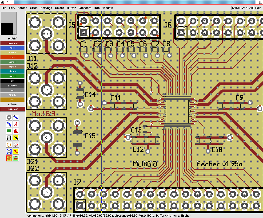
PCB 3.0 is a branch of the source code modified to operate under the Tcl/Tk interpreter. Most of the coding for PCB 3.0 was done at MultiGiG, Inc., Scotts Valley, California, by Tim Edwards, Paramesh Santanam, and (working from India, courtesy of SynApps, Inc.), Nishit Patel. The code base is a departure from the original PCB in that a complete Tcl command-line API was concocted for PCB, and the GUI re-written as a Tk script. For the first cut (version 3.0), a fair bit of effort went to ensuring that the GUI looks and acts as much like the original Xlib-based version.

Here is a screen-shot of Tcl-based PCB.

PCB version 3.0 Download

File Revision Size Date
pcb-3.0.96.tgz 96 (2623KB) February 17, 2012 at 3:00am

 source: opencircuitdesign.com

Sunday, February 26, 2012

free pcb artist layout software

|1 comments
free pcb artist layout software
FREE Printed Circuit Board Layout Software...
"PCB ARTIST™"....With Features such as "Multi-Page Schematic" and "Netlist Import" 


source: 4pcb.com

Sprint-Layout 5.0 Design your own Printed Circuit Boards

|0 comments
With Sprint-Layout you can design your PCB’s quick and easy. There is no unnecessary “ballast” which makes it difficult to keep the overview or which makes the usage almost impossible. Because of the logical and understandable structure of Sprint-Layout the usage is very easy to learn. So finally, you can concentrate to the essential thing: Designing and optimizing your PCB-layouts.
Sprint-Layout offers all needed functions to design your own layouts. Of course, there is an extensive library with all common components included.
For manufacturing your PCB’s by hand, there is an excellent printout-procedure with many options available. If you want to produce professional boards, there are many PCB-manufacturer, which accept Sprint-Layout files. If required, you can export your layout to the GERBER and EXCELLON format. Sprint-Layout is also able to create HPGL files for isolation-milling.
The new version 5.0 includes many new features and improvements, which makes the software more comfortable. As always, we take very much care of an user-friendly operation.
Of course the new version 5.0 is fully compatible to all older versions of Sprint-Layout. You can load all older layout-files and edit them with the new version.
With the free viewer-software for Sprint-Layout it is possible for everybody to view or print your layouts.
 
Sprint-Layout is equipped with tools to draw pads, tracks, copper areas, labels and so on. Just select the corresponding mode and place your elements. All parameter like track-width, pad-size, etc. are always visible at a glance, and can be edited every time. The active grid-capture lets you easily place your elements exactly.
You can edit existing layout-elements very easy. For example if you adjust the width of a track, you will see the result immediately on your layout. Additional functions like copy, move, rotate, mirror, etc. are self evident. 

sPlan 7.0 The schematic editor for Windows

|0 comments
sPlan is a software with already many thousands enthusiastic users. You need a software to design your schematic circuit diagrams easy and fast? You won’t get pass sPlan! No matter if you only want to sketch a little circuit diagram or if you need to design a big project with several pages.

The handling of sPlan is really quite simple. The components can be drawn from the extensive library to your circuit diagram. A user definable grid-capture makes it easy to place and wire the components. You can move, rotate, shear or scale all elements on your diagram just like you want. You can group several components to simplify your further work. The usual clipboard-functions let’s you copy, cut and paste any sections of your diagram. Many special features like the automatic component numbering, the component-list function, the usage of variables, the component search or the linking-functions helps you to design your schematics. Even beginners will create perfectly designed circuit diagrams within minutes.

Component libraryThe well-sorted component library contains all you need to draw a clearly arranged circuit diagram. Diodes, resistors, switches, transistors, etc. Just drag the needed components from the library to your drawing. If there is still a needed component missing, you can easily create this component and add it to the library. You may even reorganize the complete library and create symbols that exactly satisfy your demands.
You can adjust the appearance of the library, like the width or the number of displayed columns.
You can also create new libraries, which are located on network drives, so that many users can use the same library.
Download sPlan 7.0 - Viewer
source: abacom-online.de

Light alarm Mmovement Detector

|1 comments
LIGHT ALARM - 3 (MOVEMENT DETECTOR)
This circuit is very sensitive and can be placed in a room to detect the movement of a person up to 2 metres from the unit.
The circuit is basically a high-gain amplifier (made up of the first three transistors) that is turned on by the LDR or photo Darlington transistor. The  third transistor charges the 100u via a diode and this delivers turn-on voltage for the oscillator.  The LDR has equal sensitivity to the photo transistor in this circuit.

signal by-pass

|0 comments
signal by-pass
This circuit allows a class-A amplifier to drive a low impedance speaker and has a low quiescent current. The 220R in series with the speaker limits the "wasted" current to about 20mA max as the transistor is generally biased at mid-voltage. However the transistor will be almost directly driving the speaker when a signal is being processed and the only limitation is the ability of the 220R to discharge the 100u during each cycle.
The circuit is called a signal by-pass as the signal by-passes the 220R and drives the speaker directly (via the 100u). 

testing an unknown transistor

|0 comments
TESTING AN unknown TRANSISTOR

The first thing you may want to do is test an unknown transistor for COLLECTOR, BASE AND EMITTER. You also need to know if it is NPN or PNP.
You need a cheap multimeter called an ANALOGUE METER  - a multimeter with a scale and pointer (needle).
It will measure resistance values (normally used to test resistors) - (you can also test other components) and Voltage and Current. We use the resistance settings. It may have ranges such as "x10"  "x100"   "x1k"   "x10"
Look at the resistance scale on the meter. It will be the top scale.
The scale starts at zero on the right and the high values are on the left. This is opposite to all the other scales. .
When the two probes are touched together, the needle swings FULL SCALE and reads "ZERO." Adjust the pot on the side of the meter to make the pointer read exactly zero.

How to read:  "x10"  "x100"   "x1k"   "x10"
Up-scale from the zero mark is "1" 
When the needle swings to this position on the "x10" setting, the value is 10 ohms.
When the needle swings to "1" on the "x100" setting, the value is 100 ohms.
When the needle swings to "1" on the "x1k" setting, the value is 1,000 ohms = 1k.
When the needle swings to "1" on the "x10k" setting, the value is 10,000 ohms = 10k.
Use this to work out all the other values on the scale.
Resistance values get very close-together (and very inaccurate) at the high end of the scale. [This is just a point to note and does not affect testing a transistor.]
Step 1   - FINDING THE BASE  and determining NPN or PNP
Get an unknown transistor and test it with a multimeter set to "x10"
Try the 6 combinations and when you have the black probe on a pin and the red probe touches the other pins and the meter swings nearly full scale, you have an NPN transistor. The black probe is BASE
If the red probe touches a pin and the black probe produces a swing on the other two pins, you have a PNP transistor. The red probe is BASE
If the needle swings FULL SCALE or if it swings for more than 2 readings, the transistor is FAULTY. 
Step 2   - FINDING THE COLLECTOR and EMITTER
Set the meter to "x10k." 
For an NPN transistor, place the leads on the transistor and when you press hard on the two leads shown in the diagram below, the needle will swing almost full scale.   


For a PNP transistor, set the meter to "x10k"  place the leads on the transistor and when you press hard on the two leads shown in the diagram below, the needle will swing almost full scale.   


Thursday, February 23, 2012

Bridge Amplifier Car audio By using HA1377

|0 comments
HA1377 Bridge Amplifier BCL cap 17W (Car audio)
This is circuit Car audio Amplifier(Bridge Amplifier BCL) , It use IC HA1377, Supply Volt 12V-13V. Speaker 4 OHM. Nice Circuit and Easy to Build.
  Circuit HA1377 Bridge Amplifier BCL cap 17W

Tags :TA7227P, power, audio, amplifier

What is Solar Power?

|1 comments
what is solar energy?

Solar power is energy generated from the heat or light from the sun which can be used to produce heat, light, hot water, electricity, and cooling in a wide variety of applications .  When we say something is solar powered, we mean that the energy it uses was converted directly from solar energy or sunlight energy. Solar energy is often referred to as an "alternative energy" to fossil fuel energy sources such as oil and coal.

The history of photovoltaic technology

We've used the Sun for drying clothes and food for thousands of years, but only recently have we been able to use it for generating power.
The history of photovoltaic technology goes back more than one hundred years but it wasn't until the middle of the 20th century that scientists at Bell Telephone found that an element called silicon produced an electrical charge when exposed to sunlight. However, the earliest solar cells were expensive and not very efficient, converting only a fraction of the sun's light into electric current. Today, solar panel technology has vastly improved efficiency.

What is solar power offering that makes it such an appealing energy source?

•Solar energy is a completely free and inexhaustible fuel source
•No fuel, waste, or pollution is expelled in its usage.
•In remote areas, or small villages, solar power can be the saving grace. Sometimes it is the only realistic way to provide energy to a place that is not capable of drawing energy from other sources.
•It can be used for low-power purposes as well as larger ones- from battery chargers, hand-held calculators, and solar powered garden lights to air conditioning, cars, and satellites.

•Solar energy can be an integral part of any combination of clean, renewable energy sources to meet the nation's need for electricity while reducing harmful greenhouse gas emissions.
tags: solar power, solar panels, solar power systems, home solar energy, solar cell

Light Emitting Diode Part IV

|0 comments
THE RESISTOR
The value of the current limiting resistor can be worked out by Ohms Law.
Here are the 3 steps:
1. Add up the voltages of all the LEDs in a string.   e.g:  2.1v + 2.3v + 2.3v + 1.7v = 8.4v
2. Subtract the LED voltages from the supply voltage.  e.g:  12v - 8.4v = 3.6v
3. Divide the 3.6v (or your voltage) by the current through the string. 
for 25mA:   3.6/.025 =144 ohms
for 20mA:   3.6/.02  = 180 ohms
for 15mA:   3.6/.015 = 250 ohms
for 10mA:   3.6/.01   = 360 ohms
This is the value of the current-limiting resistor.

Here is a set of strings for a supply voltage of 3v to 12v and a single LED:

Here is a set of strings for a supply voltage of 5v to 12v and a white LED: 
Here is a set of strings for a supply voltage of 5v to 12v and two LEDs:

555 Timer Circuit

Power Supply

Electronic Circuit Designer.