Showing posts with label Wireless Circuit. Show all posts

Monday, January 23, 2012

FM Wireless Mike

|0 comments
 FM Wireless Mike
 
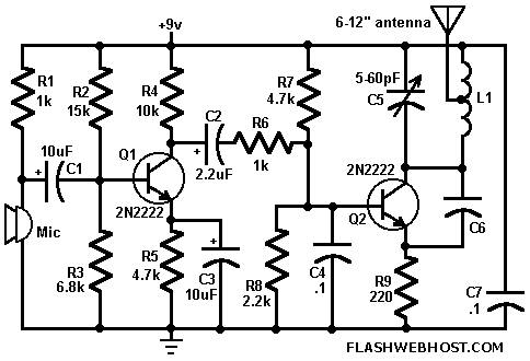
FM Wireless Mike can transmit voice signals to any FM Radio receiver 100 meters away. The circuit is basically a frequency modulated transmitter working at 100 MHz. The frequency of the transmitter can be varied slightly by changing the trimmer C5. You can use ordinary condenser mike in this circuit. The transistors can be replaced by any low power transistors like BC148 or BF494.
The coil L1 is air core 6 turn 24 SWG. Third turn is tapped and connected to telescopic antenna. You can replace telescopic antenna with a small piece of wire.
sourse: http://www.flashwebhost.com/circuit/fm_wireless_mike.php

Wireless Microphone Transmitter Receiver circuit

|0 comments
This transmitter receiver circuit is for wireless microphone. The circuit divided into two section are transmitter and receiver section. This is useful for they want to know more about transmitter receiver technically and be able to use for audio spy.

Transmitter Section
This wireless headphones transmitter assures a quality reception over 2 meters. The oscillator frequency is between 1750KHz and 3500KHz and for antenna we use a ferrite bar. IC1 amplifies the audio signal and TC1 is a buffer. D1 signals that the transmitter is on and is a voltage stabilizer for the oscillator .
L1 is a toroidal core T50-2 with 80 turns, 0.2mm Ø. L2 requires a 10-20cm ferrite bar, L2a has 3 turns, 0.6mm Ø coiled at ground end of L2b wich has 30 turns, 0.5mm Ø .

The current consumption of the wireless transmitter is 150mA and is to be used with  wireless headphones receiver.

Receiver Section

The wireless headphones receiver presented is an standard application of ZN415 produced by Ferranti (short wave receiver). ZN415 assures a quality reproduction, has a 1.5 battery alimentation and contains a MA detector and audio amplifier.

 The current consumption is  5mA, L1 has 40 turns, 0.2 Ø copper and 20mm Ø ferrite. C1 is adjusted with an non metal screw, the reception frequency of this wireless headphone receiver is between 1.7MHz and 3.4MHz – shortwave receiver. This wireless receiver is to be used with wireless headphones transmitter.

Source: Wireless headphones transmitter circuit schematic

Build A Program Remote Control

|0 comments

Build A Program Remote Control IR Transmitter Using HT6221/HT6222 IC

 Program Remote Control IR Transmitter

This project is based on integrated circuit from Holtek Semiconductor HT6221/HT6222. Similar parts used to be produced by NEC Semiconductor uPD6121/uPD6122. These ICs are commonly used in television and VCR infra red remote controls, garage door controllers, car door controllers, security systems and other remote control applications.

They are capable of encoding 16-bit address codes and 8-bit data codes. Each address/data input can be set to one of the two logic states, 0 and 1. The HT6221 can have keys up to 32(K1~K32) and HT6222 64 keys (K1~K64). When one of the keys is triggered, the programmed address/data is transmitted together with the header bits via an IR (38kHz carrier) transmission medium.

This project provides the transmitter part of the remote control. Designers and hobbyists will have to do their own software at the receiver board. Those who are familiar with microcontroller programming will find this device easy to use. The features of this IC are:

Operating voltage: 1.8V to 3.5V DC
Data output with 38kHz carrier for IR medium
Low standby current
455kHz ceramic resonator or crystal
16-bit address codes
8-bit data codes
Pulse Position Modulation code method

Program Remote Control Circuit Description

Program Remote Control Circuit Description

The typical 32 pins HT6221 schematic is as shown above. However, the values of 1k ohm and 47 ohm at the output pin 5 of the IC can be reduced to increase the distance the IR signal is transmitted. After the transmission codes are sent, the DOUT pin generates transmission codes with a carrier, and the LED goes low to drive a transmission indicator.

When one of the keys is triggered for over 36ms, the oscillator is enabled and the chip is activated. If the key is pressedand held for 108ms or less, the 108ms transmission codes are enabled and comprised of a header code (9ms), an off code (4.5ms), low byte address codes (9ms-18ms), high byte address codes (9ms-18ms), 8-bit data codes (9ms-18ms), and the inverse codes of the 8-bit data codes (9ms-18ms).

After the pressed key is held for 108ms, if the key is still held down, the transmission codes turn out to be a composition of header (9ms) and off codes (2.5ms) only.

Logic 0 is represented by timing 1.12ms and logic 1 by timing 2.24ms using pulse position modulation method as shown below.

The address code and data codes are set using the diodes 1N4148 and resistors 51K ohm and whether D7 is connected to Vcc or Ground.
The complete specifications of the Program Remote Control IC HT6221/HT6222 can be downloaded here.

Source: electronics-project-design


555 Timer Circuit

Power Supply

Electronic Circuit Designer.