Showing posts with label Electronic Circuit Designer. Show all posts

Tuesday, February 28, 2012

Download TinyCAD open source schematic

|0 comments

TinyCAD is an open source schematic capture program for MS Windows. Use TinyCAD to produce professional circuit diagrams and export net list information to PCB applications.

Description


TinyCAD is a program for drawing circuit diagrams commonly known as schematic drawings. It supports standard and custom symbol libraries. It supports PCB layout programs with several netlist formats and can also produce SPICE simulation netlists.


Features


  • Flat or Hierarchical Schematic Entry
  • Many popular PCB Layout compatible netlist formats
  • Convenient support for embedding graphical images in drawings
Download TinyCAD_2.80.03.514_Production_Setup.exe 

TinyCAD Web Site

Download free PCB design software

|5 comments

Download the easy-to-use free PCB design software. You'll be designing in minutes and get feedback on your design in seconds.
 Free PCB Layout Software
The free Pad2Pad CAD PCB layout software includes the easy-yet-powerful features you need to design your boards:
 Design Your board
  • Multiple pad types - single layer, multi-layer, vias, rectangular, round
  • Variety of trace widths
  • Foot prints - library and custom
  • Design rule checker
  • Full control of PCB views and layers
  • Move, rotate, delete objects
  • Snap to grid and snap to angle
  • Undo/Redo
  • Geometric shapes: lines, arcs, circles, polygons
  • Text with size and font control
  • Ground plane wizard
  • Logical connections (nets) - via dialog or GUI
  • Auto create nets from traces
  • Auto Routing
  • Component assembly
  • Instant pricing
  • Online ordering
  • ... and more
 Pad2Pad 1.9.72 - 02/27/2012

Download

File size: 7 MB

How to download and Install:
  1. Click Download and select Open or Run or Save File.
  2. If the installation process doesn't start, locate the downloaded setup file "p2psetup1972.exe" and execute the file.
  3. Follow the on-screen instructions to complete the installation.
 Free PCB Design Software Download 
source: www.pad2pad.com

TINA Design Suite v9

|1 comments
TINA Design Suite is a powerful yet affordable circuit simulation and PCB design software package for analyzing, designing, and real time testing of analog, digital, VHDL, MCU, and mixed electronic circuits and their PCB layouts. You can also analyze SMPS, RF, communication, and optoelectronic circuits; generate and debug MCU code using the integrated flowchart tool; and test microcontroller applications in a mixed circuit environment. A unique feature of TINA is that you can bring your circuit to life with the optional USB controlled TINALab II and LogiXplorer hardware, which turns your computer into a powerful, multifunction T&M instrument. Electrical engineers will find TINA an easy to use, high performance tool, while educators will welcome its unique features for the training environment.
  Super-fast multi-core engine. Every year, electronic circuits become faster and more complex, and therefore require more and more computational power to analyze their operation. To meet this requirement TINA v9 has the ability to utilize the increasingly popular scalable multi-thread CPUs. Computers that incorporate dual or quad core CPUs can deliver up to 20-times faster execution time for TINA’s analysis engine compared to previous versions and main competitors.
  Schematic diagram of the 4-layer SMD design
Open from the Web! Now you can open TINA designs, models and libraries as well as Import Spice .CIR and .LIB files directly from the Web. See our TINA Circuits on Web page where you will find interesting electronic circuit files and links to other websites with circuits and libraries which you can open directly from the web and then simulate with TINA.
Easy to use schematic entry. Enter any circuit within minutes with TINA's easy-to-use schematic editor. Enhance your schematics by adding text and graphics elements such lines, arcs arrows, frames around the schematics and title blocks. Choose components from the large library containing more than 20,000 manufacturer models. You can check schematics for errors with TINA’s advanced ERC functions. The schematic editor supports complex hierarchical designs, team design and version control.
Powerful analysis tools. Analyze your circuit through more than 20 different analysis modes or with 10 high tech virtual instruments. Present your results in TINA's sophisticated diagram windows, on virtual instruments, or in the live interactive mode where you can even edit your circuit during operation, develop, run, debug and test VHDL & MCU applications.
  3D view of the top side
Design Tool. This powerful tool works with the design equations of your circuit to ensure that the specified inputs result in the specified output response. The tool offers you a solution engine that you can use to solve repetitively and accurately for various scenarios. The calculated component values are automatically set in place in the companion TINA schematic and you can check the result by simulation. This new feature is also very useful for semiconductor and other electronics component manufacturers to provide application circuits along with the design procedure.
Optimization. Using TINA's built-in Optimization tool unknown circuit parameters can be determined automatically so that the network can produce a predefined target output values, minimum or maximum. Optimization is useful not only in the design of electronic circuits, but also in teaching, to construct examples and problems. It is a very good tool to refine the results provided by a design procedure or tune already working circuits.
Integrated PCB design. The new fully integrated layout module of TINA has all the features you need for advanced PCB design, including multilayer PCB’s with split power plane layers, powerful autoplacement & autorouting, rip-up and reroute, manual and ”follow-me” trace placement, DRC, forward and back annotation, pin and gate swapping, keep-in and keep-out areas, copper pour, thermal relief, fanout, 3D view of your PCB design from any angle, Gerber file output and much more.
Advanced presentation tools. Make stand-out reports and presentations of schematic diagrams, annotations, formulas provided by symbolic analysis, Bode plots, Nyquist diagrams, poles and zeros, transient responses, digital waveforms, and other data using linear or logarithmic scales. Customize presentations using TINA's advanced drawing tools to control text, fonts, axes, line width, color and layout. You can create, edit and print documents directly inside TINA or cut & paste your results into your favorite word processing or DTP package.
Importing Spice models. Create new TINA components from any Spice subcircuit, whether created by yourself, downloaded from the Internet, obtained from a manufacturer's CD or from portions of schematics turned into subcircuits. TINA automatically represents these subcircuits as a rectangular block, but you can create any shape you like with TINA's Schematic Symbol Editor. You can also use TINA's parameter extractor program to calculate model parameters from catalog or measurement data and then add the new devices into the catalog.
Educational tools. Educational tools. TINA also includes unique tools for testing students' knowledge, monitoring progress and introducing troubleshooting techniques. With optional hardware it can be used to test real circuits for comparison with the results obtained from simulation. With the Live 3D breadboard tool you can automatically build a life-like 3D picture of a solderless breadboard. When you run TINA in interactive mode, components like switches, LEDs, instruments, etc. become “live” and will work on the virtual breadboard just as in reality. You can use this capability of TINA to prepare and document lab experiments. You can also use the integrated Flowchart Editor and Debugger to generate and debug the MCU code, learning and teaching microcontroller programming.
Virtual Instruments: Oscilloscope, Function Generator, Multimeter, Signal Analyzer/Bode Plotter, Network Analyzer, Spectrum Analyzer, Logic Analyzer, Digital Signal Generator, XY Recorder.
Real time measurements. TINA is far more than a circuit simulator with virtual measurements. You can install optional, supplementary hardware that allows real-time measurements controlled by TINA's on screen virtual instruments.
TINALab II multifunction PC Instrument. With the TINALab II high speed PC instrument you can turn your laptop or desktop computer into a powerful, multifunction test and measurement instrument. Whichever instrument you need multimeter, oscilloscope, spectrum analyzer, logic analyzer, arbitrary waveform generator, or digital signal generator it is at your fingertips with a click of the mouse. In addition TINALab II can be used with the TINA circuit simulator program for comparison of circuit simulation and measurement results as a unique tool for circuit development, troubleshooting, and the study of analog and digital electronics. 
Licence : Demo
source: www.tina.com

5Spice Easy to use analog circuit simulation for the professional circuit designer

|0 comments
5Spice provides Spice specific schematic entry, the ability to define and save an unlimited number of analyses, and integrated graphing of simulation results. Plus easy inclusion of Spice/PSpice® models from a user expandable library. The focus is on analog circuit analysis and design at the component level. Student level MOSFET IC design is also supported but not compatible with HSpice® model libraries.
5Spice has the analysis capabilities needed by experienced circuit designers while remaining easy to use - a big step up from student oriented Spice programs.


Features
  • most Spice concepts are represented visually in the schematic
  • use a wizard to set Spice simulation defaults to match your circuit
  • define, name and save unlimited numbers of analyses, each with a corresponding graph
  • indexed library of Spice models and subcircuits
    easily add manufacturer's files of models and subcircuits or your own. accepts standard Spice subcircuit syntax plus almost complete compatibility with PSpice® subcircuit syntax as used by Analog Devices, Linear Technology and TI. Not compatible with PSpice digital models.
  • when linking a model to a schematic symbol, selection list shows only library models that match symbol. list is searchable and indicates any models that are not compatible.
  • subcircuit schematic symbols auto-adjust number of pins
    the opamp and generic subcircuit schematic symbols adjust the number of pins to match the number of nodes in the user selected subcircuit. users can enter names for the pins which are then saved in the library.
  • temperature or component values can be swept and results plotted in a single graph. an included opamp model allows opamp GBW to be swept.
  • no need to keep track of circuit node numbers when graphing
  • support for analysis of alternative designs
  • much of Spice's traditional quirkiness is hidden from the user
  • program's Help tells how to perform tasks, written by a Spice user
  • behavioral modeling
    schematic symbol with user defined equation (equation may contain math functions, IF-THEN-ELSE structures, etc.)
  • a notes section in the schematic and one in each analysis allows users to document their work
Distribution and license
5Spice is copyrighted software but may be used non-commercially without charge and the install program may be freely distributed. There is a 30 day evaluation period for commercial usage before registration is required. Registration licenses the program for commercial use and provides the larger schematic sizes (A,B,C size) plus the full set of features. Registered users receive priority for support and more support options.
The download is approximately 3.8 Meg and includes the WinSpice simulation engine. Once you have tried the program, check the LINKS page for manufacturers' models to download and add to the library.
System Requirements
Windows 7, Vista, XP, or Windows 2000 running on a Windows compatible computer. Also runs in Windows on Apple’s Mac computers that have an Intel processor, requires two or three button mouse. Not for Windows emulators. 800x600 or higher screen resolution recommended.
Installation Notes
Windows 7, Vista & XP
You do not need to un-install an older version of 5Spice. Starting with v1.30, 5Spice uses a different directory structure when installed in these versions of Windows. Any old program files and the model Library will be moved to the new locations.
Windows 2000: You do not need to un-install an older version of 5Spice.

self-installing  v1.65  October 31, 2011:
         Click here to download.
v1.60 includes a new version of the simulation engine specifically for 5Spice. Many bug fixes and better coordination between the two programs.


PCB version 3.0 printed circuit board layout tool

|3 comments


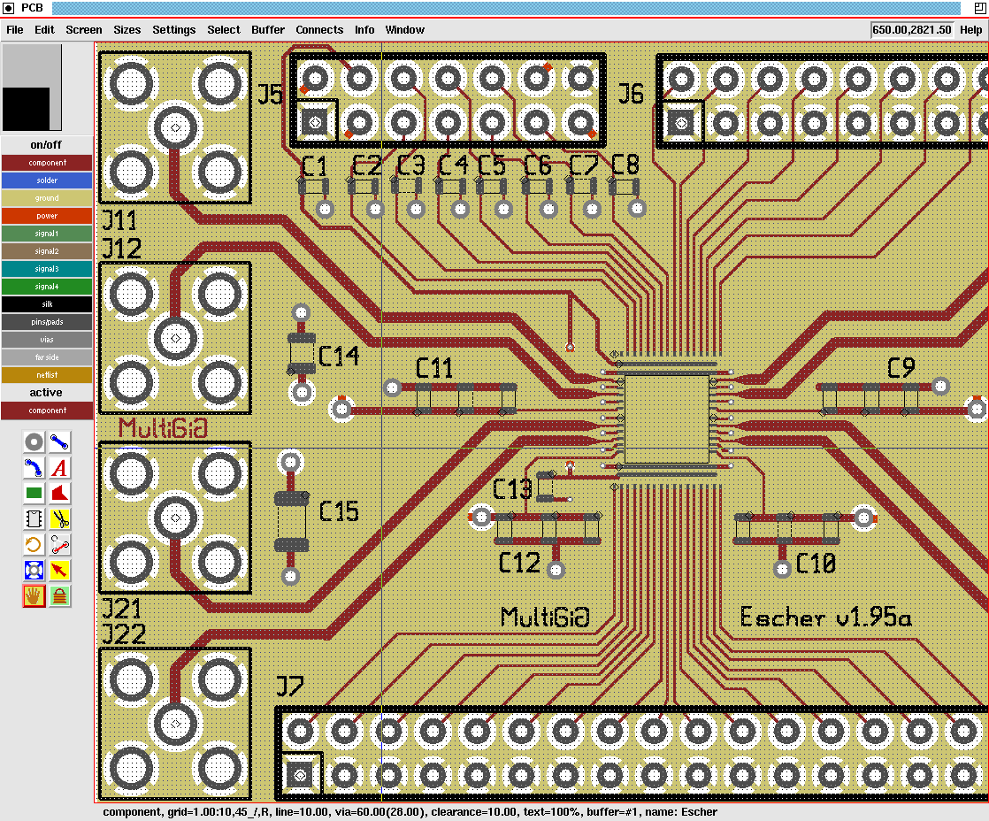
pcb is free software for designing printed circuit board layouts. It has many features and is capable of professional-quality output. It is available for UN*X operating systems, e.g., GNU/Linux, Mac OS-X, or Cygwin under Windows. pcb was orignally written by Thomas Nau of the University of Ulm, Germany, and is now maintained by harry eaton of the Johns Hopkins University Applied Physics Laboratory, Laurel, Maryland, USA.
PCB 3.0 is a branch of the source code modified to operate under the Tcl/Tk interpreter. Most of the coding for PCB 3.0 was done at MultiGiG, Inc., Scotts Valley, California, by Tim Edwards, Paramesh Santanam, and (working from India, courtesy of SynApps, Inc.), Nishit Patel. The code base is a departure from the original PCB in that a complete Tcl command-line API was concocted for PCB, and the GUI re-written as a Tk script. For the first cut (version 3.0), a fair bit of effort went to ensuring that the GUI looks and acts as much like the original Xlib-based version.

Here is a screen-shot of Tcl-based PCB.

PCB version 3.0 Download

File Revision Size Date
pcb-3.0.96.tgz 96 (2623KB) February 17, 2012 at 3:00am

 source: opencircuitdesign.com

555 Timer Circuit

Power Supply

Electronic Circuit Designer.