Wednesday, February 3, 2010

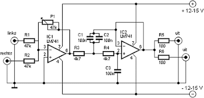
Subwoofer Filter and Low Pass Filter Circuit with LM741

|0 comments

The acoustics of converting a filter, there are many aspects of the economic viability of the more famous are

baxandal filter low and high frequency filters and crossover Acoustic space is transformed into sub-domains, so that the Thursday Speakers. Applications, we offer a filter, the limits of the region to transform acoustic (20-20000Hz) in the region of 20-100Hz.
The signal for a first high pass filter C1, C2, P1, which is undesirable level DC input. A lowpass filter consisting of R3, R4, C3 prevents frequencies above 10 kHz, which do not benefit from this design, and it would be that the instability and noise. The summary amp invert signal.

The low Summary of the amplifier signals go to a second low-pass filter to prevent the frequency from the speakers.
I decided, a second order, as this box with a closed place feature. If you have a circuit with a valve system, and then simply close the Wind (Roll a pair of socks and pick at the port / Wind), this will give you a sealed box instead.

Class-A Audio Amplifier Circuit With MOSFET IRF511

|1 comments

This circuit is that of a simple class A audio amplifier. But with zero distortion, Q1 is a switch in the on or off, so that no load current by the resistance R2. In the best case, the tension in Q1 and the load resistance must be equal to the class-A operation.
A 100K potentiometer (R3) and a 1-megohms resistance (R1) Maker a simple variable-Bias circuit. Plase voltmeter between Drain (D) of Q1 and dissemination of soil and adjust R3 for a meter to half the supply voltage.
Applications using an IRF511 has many project as it is pupola part for build the electronic circuit.
Almost every resistor value can be used for R2, as long as the maximum power and the FET are not exceeded.
A resistor value of 22 to 100 ohm is a good choice for experimentation. For high currents, a heat sink adapted to be used.

12 Segment LED Display Counter with IC 4040B

|1 comments


Part List
R1-R12 470 Ohm 1/4 Watt Resistor
R13,R14 5.6 kOhm 1/4 Watt Resistor
U1 4040B TTL BCD Counter & TTL 12 Segment Display Driver
DISP1 1 Common Anode 12 Segment LED Display
Switch
Circuit Diagram show thus as below

Picture below shows layout installation for electronic parts on PCB.
Part Installation & Wiring side
The circuit has used 12-bit binary counter which IC 4040B.
This number of the pulses of the input signal can confirmed by seeing its with the eyes by putting the light-emitting diode to the output of the counter.
The function has only of it but it is useful. As it has the 12 bits, the highest rank counter is divided to 1/4096. As it was in the highest rank, the signal of 4KHz can be seen in the about 500-millisecond blink. At the input circuit, it is protecting the counter IC from the excessive input voltage with the resistor and the Zener diode.

13.8 V High current Power supply

|0 comments

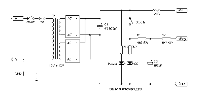
The circuit is high current power supply which is 13.8V at 20A. That, we can get base equipment which seeks to buy easy, IC LM741 ,founction one’s position voltage be stable or regulated at 13.8V.

which can fine decorate a little again. Besides still have the power transistors 2N3055 X4 numbers bring to build parallel perform enlarge current tall arrive at 20Amp Other detail , Please understand in the circuit.
13.8 high current power supply circuit 2

Time delay Relay circuit with IC555

|0 comments


Parts List
C1 10uf 16V Electrolytic Capacitor
C2 0.01uf Ceramic Disc Capacitor
R1 1 Meg Pot
R2 10 K 1/4 Watt Resistor
D1,D2 1N914 Diodes
U1 555 Timer IC
RELAY 9V Relay
S1 Normally Open Push Button Switch

Remark:
1. We used R1 adjusts the on time.

2. You can get a different capacitor for C1 to change the maximum on time.
3. S1 is used to activate the timing cycle. S1 can be replaced by a NPN transistor so that the circuit may be triggered by a computer, other circuit, etc.

Simple 12-9 volt DC to DC converter BD139

|0 comments

Description:

This circuit is a DC voltage output from a small DC input generate large voltage.It ’s easy and quick to do, and reducing the value of the Z-diode, the circuit can be universally adapted to other output devices of the circuit voltages. The give and all diagrams represent a DC converter with 12V battery 9 volt DC input and output.

With the 10V zener diode, as in the diagram, the output voltage is approximately 9.3 volts DC. The supply voltage is used, should always be at least a few volts higher than the Zener voltage. In this example, I have a 12 Volt DC battery to provide regulated 9-volt DC output.

100Watt Bipolar Power Amplifier

|0 comments

This is a basic 100 watt power amplifier designed to be (relatively) easy to build at a reasonable price.
It has a better performance (read: musical quality) than the standard STK module amps that are used in almost every mass market stereo receiver manufactured today.
When I originally built this thing, it was because I needed a 100 WPC amp and do not want any money.
So I designed around parts I had in the store.
The design is actually a standard format, and I’m sure there are commercial entities that are similar.
To my knowlwdge, it is not an exact copy of a commercial entity, nor am I aware of any patents on topology.
For experienced builders: I am aware that many improvements and adjustments can be made, but the idea was to keep it simple and must do-able by anyone who is a circuit, and has not the patience to do a sloppy job.

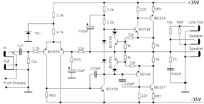
If friend want Bipolar Transistor power amplifier circuit. , In model HIFI OCL 100W RMS.
I think this track should be an interesting choice, this circuit is the use of the key transistor BD317 and BD318 unless
transistor number BD139, BD140, BC556 too easy then try to buy when the 35V power source with only then build is not difficult for other details as the result of a few See Circuit.

Input stage is a BC556 transistor, which most of the open loop gain, and on the serene DC voltage stabilizes.
This feeds a level shift stage where the voltage swing to (-) track references. The Transconductance stage is a Darlington, improve frerqency high linearity. The BD317, 318 on a rather large collector-base capacity is dependent on voltage.
The BD319 presents this low-z and has a C (ob) of only a few of PF, which is effectively swamped by the pole-splitting 220pF cap.
The scene is supplied by BC546 active load (current), which is approximately 20 mA.
The current, until the BC556 is limited to about 70 mA in the worst cases.

50W Audio Power Amplifier with IC TDA1514A

|0 comments
Here is circuit audio amplifiers for car, which use it only number Transistor Circuit of IC, simple Circuit (and Top Popula)

Use TDA1514A transistor at low cost. It best Idea Circuit.

It’s receive a handful of additional external device in comparison to the generic diagram. Remember that there’s a simple HF filter on input signal. This IC supports mute and stand-by modes. I have not built this one, so I have get no suggestions concerning practical construction.


Remark:
Supply Voltage = +/- 30V
Ur = 0-1V : Stand by
= 2-4.5V : Mute
= 6-7V : Play

Auto Cooling Fan Circuit With IC LM741

|0 comments

This circuit is auto fan or cooling fan for your computer,electronic project,the circuit is simply to apply to your project .

Couple Notes:

Th1, the 50K thermistor is a standard type. I was looking for a bar or rectangular thingy. Available from Tandy / Radio Shack. Almost any type will do. I experimented with different models of 22K to 100K and everything worked fine after replacing the trimmer pot and a little “tuning.

The one used in the diagram above circuit has been a model of 50K by Fenwal (# 197-503LAG-A01). The 50K was measured exactly at 25 ° C and a tolerance of 10%. The increase in resistance as temperatures fall. Tolerance for my application (cooling a PowerSupply coolrib wide) is 10%.
Another name for this thing is “NTC”. NTC stands for “negative temperature coefficient” which means that when the temperature decreases the resistance of the thermistor will increase. You may need to shop for the lowest price. Some are thermistor may have a minimum of $ 4.00, but for $ 55.00 Canadian dollars for the type of glass encapsulated (best).
I replaced my 60K thermistor for a type of glass hermetically sealed such as the environment so that my application may contain corrosive particles that can affect performance at a future date.

Bourns trimmer P1 is an ordinary rule and a wide temperature range of this circuit. I used the 10-ballot style for a little fine tuning, but the kind of regular job application.

R1 is a “security” of resistance where the pot P1 trimmer is adjusted all the way to ‘0 ‘ohm. Just then the thermistor would receive the full 12 volts and so hot that puts blisters on your fingers …
R3 feeds back a little in the hysteresis op-amp to eliminate the chattering relay, when the temperature of the thermistor reaches its threshold. Depending on the application and the type used in Q1 and Re1, start with about 330K and reduce its value until satisfied. The value of 150K reported in the scheme worked for me. Reducing the value of hysteresis R2 more resources, just do not use more than necessary. Or temporarily use a trimmer pot and read the value. 120K worked for me.

Transistor Q1 may be a 2N2222 (A) 2N3904, NTE123A, ECG123A, etc. not critical at all. It only acts as a switch for the relay in almost any type will work, until he could provide the current necessary to activate the relay coil.

D1, 1N4148, acts as a spark arrestor when the relay contacts open and eliminates false triggering. For my application, the 1N4148 was good for the relay I used only 1 Amps small. However, you can use a variety of diodes here, my next choice would be a regular target 1N4001 or something and should be used if the type of relay that can handle more than 1 ampere.

Digagram circuit, PCB and layout are up to date with C1, C2, R7 and LED. C1 and C2 are new to eliminate the switching noise of the relay in some applications. The optional LED, and resistance were added to the circuit and layot for your convenience. The relay used in this and the kit is a type 12V/0.5A small. If the relay rattles increase the feedback resistor R3 to 180K or a little “higher, and small ceramic cap on the coil connections in parallel with the diode D1. Diode 1N4148 is specified for a small relay. If you use a relays used as a 1N4001 or 1N4004.

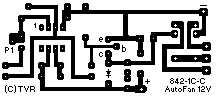
If you like to make your own PCBs, try the following. The PCB is equipped with holes for the relay, but may not take your particular relay. It was designed for a type Aromat HB1 DC12V. The variety and model of the relay is only for adults. How to mount then? Well, I left a lot of space on the PCB to mount your relay. You can also mount below, and connect the cables individually. The use of silicone adhesive, cyanoacrylate ester (crazy glue) or double-sided tape to hold the relay in place. Works well. Note that the PAC and the setting Page Not according to the circuit diagram regarding the coupling of fans. The PCB is about 1.5 x 3 inches (4.8 x 7.6 mm)
If you print a PCB inkjet printer is probably not to scale. Try to mount an 8-pin IC socket on a printed copy to ensure it matches the scale before printing on a sheet of transparency and make the PCB …

Auto Fan PCB Picture

Part , Description , Radio Shack , Digi Key , Newark Notes
IC1 LM741 Op-Amp 276-007 LM741CN-ND LM741CN NE741,µA741, etc.
Q1 2N2222A transistor 276-2009 2N2222A-ND 2N3904 See text
D1 1N4148 Diode 276-1122 1N4148GICT-ND 1N4001 1N4001, or others
Th1 50K Thermistor KC005T-ND 96F3309 KC005T in prototype
Re1 12V Relay 275-249 Z753-ND 83F8057 RS is 1A
R1 15K, 5% resistor 84N2487 brown-green-orange
R2,R5 10K, 5% resistor 84N2479 brown-black-orange
R3 150K, 5% resistor 84N2485 brown-green-yellow
R4 4K7, 5% resistor 271-1330 50N1628 yellow-purple-red
R6 1K, 5% resistor 271-1321 50N6012 brown-black-red
R7 1K8, 5% resistor brown-gray-red
P1 100K Trimmer Pot Bourns
C1 10uF/25V Capacitor Electrolytic
C2 0.01uF, Capacitor Ceramic
Led Red, 3mm Light Emitting Diode

Auto Fan Part on Board

Spare parts:

Q1 = 2N3053, 2N3904, NTE123A, ECG123A, NTE128, ECG128, etc.
D1 = 1N4001, NTE519, ECG519, NTE116 etc.
Th1 = Thermistor, 22K – 100K. 50K used in the prototype.
Re1 = Relay, Type 842-1C-C “Fashion Electronics. Order # 50-333-0 (1.55 $)
Reed relay works well.

Thank for good circuit :

http://www.uoguelph.ca/~antoon/circ/auto-fan.html

40 Watt Power Amplifier Circuit With TDA2030

|0 comments

Power is 22W into 8 ohm speakers and 40W into 4 ohms. Distortion is 0.012% at 1 kHz / 8 ohm/11W and 0.032% at 1 kHz / 4 ohm/20W. Curent Offers variates IC1 ultimately for the input audio signal, so there will be a similar variation on the R6, R7, R8 and R9. Until the current is close to 1A, voltage resistance is not enough to open the T1 and T2. This means that the performance is less than 2 W into 4 ohm output of the TDA2030. This is a great audio power amplifier, because I know how to create them.
Supply voltage is between 12V and 40V.
Large 40 W mono audio amplifier with built TDA 2030, BD 712 BD 711th

40w power amplifier pcb

25Watt Hifi Amplifier

|0 comments

Electronic project contains the essential elements for building a HiFi Amp module using the LM1875 chip.

This project contains the essential elements needed to build an amplifier module for high fidelity with the National Semiconductor LM1875 IC. With the addition of a handful of parts and an adequate supply, this module provides 25W RMS into 8 ohms @ 1% THD.

PCB dimensions are a tiny 53 x 50mm (2.1 “x 2″). Heatsink, power transformer, speaker and cables are not included. (CPS50)
This project contains the essential elements needed to build an amplifier module for high fidelity with the National Semiconductor LM1875 IC. With the addition of a handful of parts and an adequate supply, this module provides 25W RMS into 8 ohms @ 1% THD.
The project is built on a single side PCB. Protel Schematic & Autotrax were used in conception.

25 Watt LM1875 Implementation of components containing PCBs
Data to be provided to you:

Heat sink with a thermal resistance of 1.4 C / W or higher. Use the washing of silicon impregnated in the event of attack on the chip.
Speaker 8 ohm adequate power
Suitable cables.
Solder the power cables and audio directly on the pad provided on the PCB.
The chip can be used with two agreements that provide single and dual power. We decided to use the dual fuel version. Version only offering that require the use of electrolytic capacitors 63V, thus increasing the cost and overall size of the module.

The input signal is coupled with R1 and C1 for the non-inverting input (pin 1) of the integrated circuit. Closed-loop gain of the amplifier is set at 19 by resistors (180K) and (10K). and C (22uF) in 3dB frequency point 7Hz.

The output appears on pin 4 of IC and drives a speaker directly. Speakers can produce long enough capacity to drive the amplifiers in the VHF oscillation. Resistance R6 (1W) and capacitor C4 (0.22UF) to help prevent this. They are linked through the production and the form of a Zobel network, which provides high frequency stability when driving capacitive loads.

The power supply integrated circuit is connected via 2A fuse for protection against external shorts to ground. Provide additional decoupling capacitors Supply Board.

The module is powered by a dual + / – 25V supply. These guides are provided by a separate power supply board. Consists of four diodes (1N5401) connected as a rectifier bridge and four electrolytic capacitors (2200uF) to soften wrinkles.

The power transformer used to power the module should be assessed at 60VA with a center-operated 35V secondary winding. A 30V transformer secondary winding can also be used, but the lower output DC would lead to reduced power.

If you want to run two modules in a stereo amplifier, you can use a common food. In this case, the RANSFORMER should be valued at 80VA.

Test

Before the switch, verify that all parts are inserted in the correct positions. Make sure that the electrolytic capacitors are in the right direction. Connect the power leads with a multimeter (set to read amps) in series with the positive rail. Do not connect a speaker or an audio input yet.

Turn on and check the current stabilizes at 50-70mA. There will be a brief charges that Suge main filter capacitor. You must have installed the radiator, otherwise the overload protection circuit to reduce the heat in and out.

If the quiescent current is correct, check the DC offset voltage at the terminals of the speakers. It must be less than + / – 50mV. If all goes well, switch off the device and connect a speaker and an audio signal input.
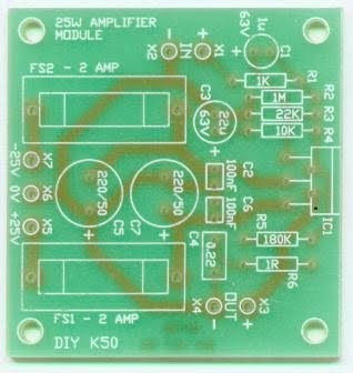
25Watt Hifi Amplifier PCB
555 Timer Circuit

Power Supply

Electronic Circuit Designer.